Jeep Grand Cherokee WK. Manual - part 1188


  Index      Jeep     Jeep Grand Cherokee WK - service repair manual 2005 year


Search            


Content   ..  1186  1187  1188  1189   ..


Jeep Grand Cherokee WK. Manual - part 1188


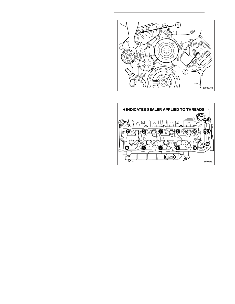
18. Remove the cylinder head access plug (1).

19. Remove the right side secondary chain guide

(Refer to 9 - ENGINE/VALVE TIMING/TIMING
BELT/CHAIN AND SPROCKETS - REMOVAL).

20. Remove the retaining bolt and the camshaft drive

gear.

CAUTION: Do not allow the engine to rotate.
severe damage to the valve train can occur.

CAUTION: Do not overlook the four smaller bolts
at the front of the cylinder head. Do not attempt to
remove the cylinder head without removing these
four bolts.

CAUTION: Do not hold or pry on the camshaft tar-
get wheel for any reason. A damaged target wheel
can result in a vehicle no start condition.

NOTE: The cylinder head is attached to the cylin-
der block with fourteen bolts.

21. Remove the cylinder head retaining bolts using

the sequence provided.

22. Remove the cylinder head and gasket. Discard the gasket.

CAUTION: Do not lay the cylinder head on its gasket sealing surface, do to the design of the cylinder head
gasket any distortion to the cylinder head sealing surface may prevent the gasket from properly sealing
resulting in leaks.

CLEANING

To ensure engine gasket sealing, proper surface preparation must be performed, especially with the use of alumi-
num engine components. (Refer to 9 - ENGINE - STANDARD PROCEDURE)

INSPECTION

1. Inspect the cylinder head for out-of-flatness, using a straightedge and a feeler gauge. If tolerances exceed

0.0508 mm (0.002 in.) replace the cylinder head.

2. Inspect the valve seats for damage. Service the valve seats as necessary.

3. Inspect the valve guides for wear, cracks or looseness. If either condition exist, replace the cylinder head.

9 - 1348

ENGINE - 4.7L SERVICE INFORMATION

WK

INSTALLATION - RIGHT CYLINDER HEAD

NOTE: The cylinder head bolts are tightened using
a torque plus angle procedure. The bolts must be
examined

BEFORE

reuse.

If

the

threads

are

necked down (2) the bolts should be replaced.

Necking (2) can be checked by holding a straight
edge against the threads. If all the threads do not con-
tact the scale (2), the bolt should be replaced.

CAUTION: When cleaning cylinder head and cylin-
der block surfaces, DO NOT use a metal scraper
because the surfaces could be cut or ground. Use
only a wooden or plastic scraper (1).

1. Clean the cylinder head and cylinder block mating

surfaces.

2. Position the new cylinder head gasket on the locat-

ing dowels.

CAUTION: When installing cylinder head, use care
not damage the tensioner arm or the guide arm.

3. Position the cylinder head onto the cylinder block.

Make sure the cylinder head seats fully over the
locating dowels.

NOTE: The four smaller cylinder head mounting
bolts require sealant to be added to them before
installing. Failure to do so may cause leaks.

4. Lubricate the cylinder head bolt threads with clean

engine oil and install the ten M10 bolts.

5. Coat the four M8 cylinder head bolts with Mopar

T

Lock and Seal Adhesive then install the bolts.

NOTE: The cylinder head bolts are tightened using an angle torque procedure, however, the bolts are not a
torque-to-yield design.

WK

ENGINE - 4.7L SERVICE INFORMATION

9 - 1349

6. Tighten the bolts in sequence using the following steps and torque values:

Step 1: Tighten bolts 1–10, 20 N·m (15 ft. lbs.).

Step 2: Tighten bolts 1–10, 47 N·m (35 ft. lbs.). Tighten bolts 11–14, 25 N·m (18 ft. lbs.).

Step 3: Tighten bolts 1–10, 90 degrees. Tighten bolts 11–14, 30 N·m (22 ft. lbs.).

7. Position the secondary chain onto the camshaft drive gear, making sure one marked chain link is on either side

of the V8 mark on the gear (2) and position the gear onto the camshaft.

8. Install the camshaft drive gear retaining bolt.

9. Install the right side secondary chain guide (Refer to 9 - ENGINE/VALVE TIMING/TIMING BELT / CHAIN COV-

ER(S) - INSTALLATION).

10. Install the right side cylinder head access plug (1).

11. Re-set and install the right side secondary chain

tensioner.

9 - 1350

ENGINE - 4.7L SERVICE INFORMATION

WK

12. Remove Special Tool 8515 (6).

13. Install the timing chain cover (Refer to 9 -

ENGINE/VALVE TIMING/TIMING BELT / CHAIN
COVER(S) - INSTALLATION).

14. Install the crankshaft damper (Refer to 9 -

ENGINE/ENGINE BLOCK/VIBRATION DAMPER -
INSTALLATION).

15. Install accessory drive belt (Refer to 7 - COOL-

ING/ACCESSORY

DRIVE/DRIVE

BELTS

-

INSTALLATION).

16. Install the fan shroud.

17. Install the cylinder head cover (1) (Refer to 9 -

ENGINE/CYLINDER

HEAD/CYLINDER

HEAD

COVER(S) - INSTALLATION).

18. Install the intake manifold (Refer to 9 - ENGINE/

MANIFOLDS/INTAKE MANIFOLD - INSTALLA-
TION).

19. Install oil fill housing onto cylinder head.

20. Refill the cooling system (Refer to 7 - COOLING -

STANDARD PROCEDURE).

21. Raise the vehicle.

22. Install the exhaust pipe onto the right exhaust

manifold.

23. Lower the vehicle.

24. Reconnect battery negitive cable.

25. Start the engine and check for leaks.

CAMSHAFT - RIGHT

DESCRIPTION

The camshafts consist of powdered metal steel lobes which are sinter-bonded to a steel tube. A steel post or nose
piece is friction-welded to the steel camshaft tube. Five bearing journals are machined into the camshaft, four on the
steel tube and one on the steel nose piece. Camshaft end play is controlled by two thrust walls that border the nose
piece journal. Engine oil enters the hollow camshafts at the third journal and lubricates every intake lobe rocker
through a drilled passage in the intake lobe.

WK

ENGINE - 4.7L SERVICE INFORMATION

9 - 1351


Content   ..  1186  1187  1188  1189   ..