Jeep Grand Cherokee WK. Manual - part 1184


  Index      Jeep     Jeep Grand Cherokee WK - service repair manual 2005 year


Search            


Content   ..  1182  1183  1184  1185   ..


Jeep Grand Cherokee WK. Manual - part 1184


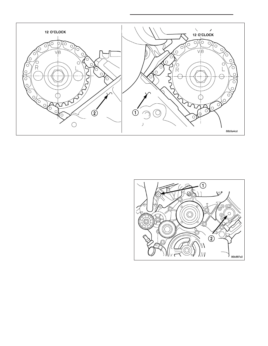
7. Position the secondary chain onto the camshaft drive gear, making sure one marked chain link is on either side

of the V8 mark on the gear and position the gear onto the camshaft.

8. Install the camshaft drive gear retaining bolt.

9. Install the left side secondary chain guide (Refer to 9 - ENGINE/VALVE TIMING/TIMING BELT/CHAIN AND

SPROCKETS - INSTALLATION).

10. Install the cylinder head access plug (2).

11. Re-set and Install the left side secondary chain

tensioner (Refer to 9 - ENGINE/VALVE TIMING/
TIMING

BELT/CHAIN

AND

SPROCKETS

-

INSTALLATION).

9 - 1332

ENGINE - 4.7L SERVICE INFORMATION

WK

12. Remove Special Tool 8515 (6).

13. Install the timing chain cover (Refer to 9 -

ENGINE/VALVE TIMING/TIMING BELT / CHAIN
COVER(S) - INSTALLATION).

14. Install the crankshaft damper (Refer to 9 -

ENGINE/ENGINE BLOCK/VIBRATION DAMPER -
INSTALLATION).

15. Install the power steering pump.

16. Install the fan blade assembly and fan shroud

(Refer to 7 - COOLING/ENGINE/FAN DRIVE VIS-
COUS CLUTCH - INSTALLATION).

17. Install the cylinder head cover (Refer to 9 -

ENGINE/CYLINDER

HEAD/CYLINDER

HEAD

COVER(S) - INSTALLATION).

18. Reinstall the master cylinder and booster assem-

bly. Refer to section 5 brakes.

19. Install the intake manifold (Refer to 9 - ENGINE/

MANIFOLDS/INTAKE MANIFOLD - INSTALLA-
TION).

20. Refill the cooling system (Refer to 7 - COOLING -

STANDARD PROCEDURE).

21. Raise the vehicle.

22. Install the exhaust pipe onto the left exhaust man-

ifold.

23. Lower the vehicle.

24. Connect the negative cable to the battery.

25. Start the engine and check for leaks.

CAMSHAFT - LEFT

DESCRIPTION

The camshafts consist of powdered metal steel lobes which are sinter-bonded to a steel tube. A steel post or nose
piece is friction-welded to the steel camshaft tube. Five bearing journals are machined into the camshaft, four on the
steel tube and one on the steel nose piece. Camshaft end play is controlled by two thrust walls that border the nose
piece journal. Engine oil enters the hollow camshafts at the third journal and lubricates every intake lobe rocker
through a drilled passage in the intake lobe.

WK

ENGINE - 4.7L SERVICE INFORMATION

9 - 1333

REMOVAL

1. Remove cylinder head cover (1) (Refer to 9 -

ENGINE/CYLINDER

HEAD/CYLINDER

HEAD

COVER(S) - REMOVAL).

CAUTION: When the timing chain is removed and the cylinder heads are still installed, DO NOT forcefully
rotate the camshafts or crankshaft independently of each other. Severe valve and/or piston damage can
occur.

CAUTION: When removing the cam sprocket, timing chains or camshaft, Failure to use Special Tool 8350
will result in hydraulic tensioner ratchet over extension, requiring timing chain cover removal to reset the
tensioner ratchet.

2. Set engine to TDC cylinder #1, camshaft sprocket V8 marks at the 12 o’clock position (1).

3. Mark one link on the secondary timing chain on both sides of the V8 mark on the camshaft sprocket to aid in

installation.

CAUTION: Do not hold or pry on the camshaft target wheel (Located on the right side camshaft sprocket)
for any reason, Severe damage will occur to the target wheel resulting in a vehicle no start condition.

4. Loosen but DO NOT remove the camshaft sprocket retaining bolt. Leave the bolt snug against the sprocket.

9 - 1334

ENGINE - 4.7L SERVICE INFORMATION

WK

NOTE: The timing chain tensioners must be secured prior to removing the camshaft sprockets. Failure to
secure tensioners will allow the tensioners to extend, requiring timing chain cover removal in order to reset
tensioners.

CAUTION: Do not force wedge past the narrowest point between the chain strands. Damage to the tension-
ers may occur.

5. Position Special Tool 8350 (4) timing chain wedge between the timing chain strands, tap the tool to securely

wedge the timing chain against the tensioner arm and guide.

NOTE: When gripping the camshaft, place the pli-
ers on the tube portion of the camshaft only. Do
not grip the lobes or the sprocket areas.

6. Hold the camshaft (3) with adjustable pliers (2)

while removing the camshaft sprocket bolt and
sprocket (1).

7. Using the pliers, gently allow the camshaft to rotate

15° clockwise until the camshaft is in the neutral
position (no valve load).

WK

ENGINE - 4.7L SERVICE INFORMATION

9 - 1335


Content   ..  1182  1183  1184  1185   ..