Jeep Grand Cherokee WK. Manual - part 115


  Index      Jeep     Jeep Grand Cherokee WK - service repair manual 2005 year


Search            


Content   ..  113  114  115  116   ..


Jeep Grand Cherokee WK. Manual - part 115


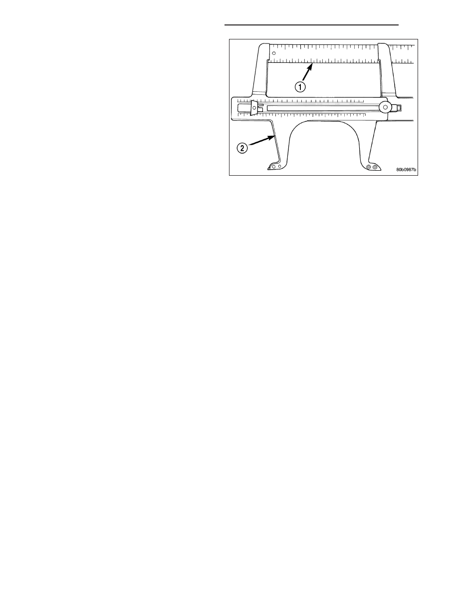
7. Reduce the inside diameter measurement of the

brake drum that was taken using Special Tool
C-3919 (2) by 1/64 of an inch. Reset Gauge, Brake
Shoe, Special Tool C-3919 (2) or the equivalent
used, so that the outside measurement jaws are
set to the reduced measurement.

8. Place Gauge, Brake Shoe, Special Tool C-3919 (2)

, or equivalent over the park brake shoes. The spe-
cial tool must be located diagonally across at the
top of one shoe and bottom of opposite shoe (wid-
est point) of the park brake shoes.

9. Using the star wheel adjuster, adjust the park brake

shoes until the lining on the park brake shoes just
touches the jaws on the special tool.

10. Repeat step 8 above and measure shoes in both

directions.

11. Install brake rotor on the axleshaft (Refer to 5 - BRAKES/HYDRAULIC/MECHANICAL/ROTORS - INSTALLA-

TION).

12. Rotate rotor to verify that the park brake shoes are not dragging on the brake drum. If park brake shoes are

dragging, remove rotor and back off star wheel adjuster one notch and recheck for brake shoe drag against
drum. Continue with the previous step until brake shoes are not dragging on brake drum.

13. Install disc brake caliper on caliper adapter (Refer to 5 - BRAKES/HYDRAULIC/MECHANICAL/DISC BRAKE

CALIPERS - INSTALLATION).

14. Install wheel and tire.

15. Tighten the wheel mounting nuts in the proper sequence until all nuts are torqued to half the specified torque.

Then repeat the tightening sequence to the full specified torque of 129 N·m (95 ft. lbs.).

16. Lower vehicle.

CAUTION: Before moving vehicle, pump brake pedal several times to ensure the vehicle has a firm enough
pedal to stop the vehicle.

NOTE: After parking brake lining replacement, it is recommended that the parking brake system be condi-
tioned prior to use. This is done by making one stop from 25 mph on dry pavement or concrete using light
to moderate force on the parking brake hand lever.

17. Road test the vehicle to ensure proper function of the vehicle’s brake system.

ADJUSTMENT - WITH ADJUSTING TOOL

Adjustment can be made with a standard brake gauge or with adjusting tool. Adjustment is performed with the com-
plete brake assembly installed on the backing plate.

1. Be sure parking brake lever is fully released.

2. Raise vehicle so rear wheels can be rotated freely.

3. Remove plug from each access hole in brake support plates.

4. Loosen parking brake cable adjustment nut until there is slack in front cable.

5. Insert adjusting tool through support plate access hole and engage tool in teeth of adjusting screw star wheel.

5 - 86

BRAKES - BASE - SERVICE INFORMATION

WK

6. Rotate adjuster screw star wheel (move tool handle

upward) until slight drag can be felt when wheel is
rotated.

7. Push and hold adjuster lever away from star wheel

with thin screwdriver.

8. Back off adjuster screw star wheel until brake drag

is eliminated.

9. Repeat adjustment at opposite wheel. Be sure

adjustment is equal at both wheels.

10. Install support plate access hole plugs.

11. Adjust parking brake cable and lower vehicle.

12. Depress park brake lever and make sure park

brakes hold the vehicle staionary.

13. Release park brake lever.

WK

BRAKES - BASE - SERVICE INFORMATION

5 - 87

BRAKES - ABS - SERVICE INFORMATION

TABLE OF CONTENTS

page

page

BRAKES - ABS - SERVICE INFORMATION

DESCRIPTION

ANTILOCK BRAKE SYSTEM WITH

TRACTION CONTROL . . . . . . . . . . . . . . . . . . 89

ELECTRONIC STABILITY PROGRAM

. . . . . . 89

ELECTRONIC VARIABLE BRAKE

PROPORTIONING . . . . . . . . . . . . . . . . . . . . . 90

OPERATION

ANTILOCK BRAKE SYSTEM WITH

TRACTION CONTROL . . . . . . . . . . . . . . . . . . 90

ELECTRONIC STABILITY PROGRAM

. . . . . . 91

ELECTRONIC VARIABLE BRAKE

PROPORTIONING . . . . . . . . . . . . . . . . . . . . . 92

DIAGNOSIS AND TESTING - ANTILOCK

BRAKES

. . . . . . . . . . . . . . . . . . . . . . . . . . . . 92

STANDARD PROCEDURE - BLEEDING ABS

BRAKE SYSTEM

. . . . . . . . . . . . . . . . . . . . . . 92

SPECIFICATIONS

TORQUE CHART

. . . . . . . . . . . . . . . . . . . . . . 93

SENSOR-FRONT WHEEL SPEED

DESCRIPTION

. . . . . . . . . . . . . . . . . . . . . . . . . 93

OPERATION

. . . . . . . . . . . . . . . . . . . . . . . . . . . 93

REMOVAL

. . . . . . . . . . . . . . . . . . . . . . . . . . . . . 93

INSTALLATION

. . . . . . . . . . . . . . . . . . . . . . . . . 94

SENSOR-REAR WHEEL SPEED

DESCRIPTION

. . . . . . . . . . . . . . . . . . . . . . . . . 95

OPERATION

. . . . . . . . . . . . . . . . . . . . . . . . . . . 95

REMOVAL

. . . . . . . . . . . . . . . . . . . . . . . . . . . . . 96

INSTALLATION

. . . . . . . . . . . . . . . . . . . . . . . . . 97

SENSOR-BRAKE PRESSURE

REMOVAL

. . . . . . . . . . . . . . . . . . . . . . . . . . . . . 98

INSTALLATION

. . . . . . . . . . . . . . . . . . . . . . . . . 98

SENSOR-DYNAMICS

DESCRIPTION

. . . . . . . . . . . . . . . . . . . . . . . . . 99

REMOVAL

. . . . . . . . . . . . . . . . . . . . . . . . . . . . . 99

INSTALLATION

. . . . . . . . . . . . . . . . . . . . . . . . 100

SENSOR-STEERING ANGLE

DESCRIPTION

. . . . . . . . . . . . . . . . . . . . . . . . 100

REMOVAL

. . . . . . . . . . . . . . . . . . . . . . . . . . . . 100

INSTALLATION

. . . . . . . . . . . . . . . . . . . . . . . . 100

SENSOR-G

DESCRIPTION

G-SENSOR - WITH ESP

. . . . . . . . . . . . . . . 101

G-SENSOR - WITHOUT ESP

. . . . . . . . . . . . 101

HCU (HYDRAULIC CONTROL UNIT)

DESCRIPTION

. . . . . . . . . . . . . . . . . . . . . . . . 102

OPERATION

. . . . . . . . . . . . . . . . . . . . . . . . . . 102

REMOVAL

. . . . . . . . . . . . . . . . . . . . . . . . . . . . 102

INSTALLATION

. . . . . . . . . . . . . . . . . . . . . . . . 104

BOOSTER-ACTIVE BRAKE

DESCRIPTION

. . . . . . . . . . . . . . . . . . . . . . . . 106

5 - 88

BRAKES - ABS - SERVICE INFORMATION

WK

BRAKES - ABS - SERVICE INFORMATION

DESCRIPTION

ANTILOCK BRAKE SYSTEM WITH TRACTION CONTROL

This vehicle uses the MK25 Antilock braking system
(ABS). This system, a combined ABS and Traction
Control system is standard on some vehicles and
optional on others.

This antilock brake system uses components of the
base brake system, but also features the following
components:

Integrated Control Unit (ICU) - Includes Hydraulic
Control Unit (HCU) (2) and Antilock Brake Mod-
ule (ABM) (3)

Wheel Speed Sensors (WSS) - Four sensors
(one at each wheel)

ABS

The purpose of the antilock brake system (ABS) is to prevent wheel lockup under braking conditions on virtually any
type of road surface. Antilock braking is desirable because a vehicle that is stopped without locking the wheels
retains directional stability and some steering capability. This allows the driver to retain greater control of the vehicle
during braking.

ALL-SPEED TRACTION CONTROL

The traction control system is an all-speed traction control. All-Speed Traction Control enhances mobility and pre-
vents wheel slip when accelerating on slippery surfaces. Depending on how slippery, an automatically activated
Winter Mode feature will select lower transmission up-shift speeds. It also provides a measure of directional stability
control. Using the wheel-speed sensors, it can detect excessive yaw and help keep the car on the intended course,
as for instance, when accelerating around a curve.

With rear-wheel drive, All-Speed Traction Control is effective up to 85 mph (137 km/h); with AWD, All-Speed Traction
Control is effective up to 45 mph (72 km/h), which is common among competitive AWD vehicles with traction control.

ELECTRONIC STABILITY PROGRAM

ESP

T

(Electronic Stability Program), which includes a Brake Assist feature, is standard on some models and

optional on others. ESP aids the driver in maintaining vehicle directional stability. ESP will do whatever can be done,
within the limits of available traction, to keep the car on course.

ESP uses the ABS with Traction Control allong with the following components to operate:

Active Brake Booster

Brake Pressure Switch

Dynamics Sensor

Steering Angle Sensor (SAS)

The Active Brake Booster is part of the Power Brake Booster. The Brake Pressure Switch is mounted to the bottom
of the Master Cylinder. The Dynamics Sensor that is mounted under the center console, which is near the center of
gravity of the car for effective sensing. TheTravel Sensor is mounted in the Power Brake Booster. The Steering
Angle Sensor is located in the steering column.

WK

BRAKES - ABS - SERVICE INFORMATION

5 - 89


Content   ..  113  114  115  116   ..