Jeep Grand Cherokee WK. Manual - part 1121


  Index      Jeep     Jeep Grand Cherokee WK - service repair manual 2005 year


Search            


Content   ..  1119  1120  1121  1122   ..


Jeep Grand Cherokee WK. Manual - part 1121


P3442–CYLINDER 6 DEACTIVATION CONTROL PERFORMANCE (CONTINUED)

3.

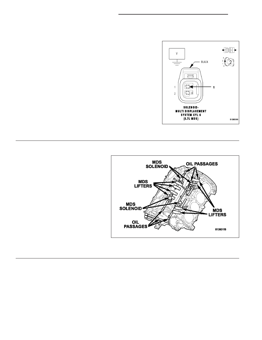
(K453) MDS SOLENOID NO.6 CONTROL CIRCUIT SHORTED TO VOLTAGE

Turn the ignition off.

Disconnect the C2 PCM harness connector.

Turn the ignition on.

Measure the volage of the (K453) MDS Solenoid No.6 Control circuit
in the MDS Solenoid No.6 harness connector.

Is voltage present?

Yes

>> Repair the short to voltage in the (K453) MDS Solenoid

No.6 Control circuit.

Perform the POWERTRAIN VERIFICATION TEST. (Refer
to 9 - ENGINE - STANDARD PROCEDURE)

No

>>

NOTE: Before continuing, check the PCM harness connector ter-
minals for corrosion, damage, or terminal push out. Repair as
necessary.Replace and program the Powertrain Control Module
per Service Information.

Perform the POWERTRAIN VERIFICATION TEST. (Refer to 9 - ENGINE - STANDARD PROCEDURE)

4.

MDS SOLENOID 6

Turn the ignition off.

Remove the Intake Manifold per Service
Information.

Turn the ignition on.

With the scan tool actuate the MDS Sole-
noid 6.

Can you feel and hear the Solenoid
Actuating?

Yes

>> Go To 5

No

>> Remove

the

Solenoid

and

check for any debris that may
be blocking the oil passages to
the Solenoid. If the passages
are clogged, clean the pas-
sages and replace the MDS
Solenoid 6. If the passages are not clogged with debris, replace the MDS Solenoid 6.

Perform the POWERTRAIN VERIFICATION TEST. (Refer to 9 - ENGINE - STANDARD PROCEDURE)

9 - 1080

ENGINE ELECTRICAL DIAGNOSTICS

WK

P3442–CYLINDER 6 DEACTIVATION CONTROL PERFORMANCE (CONTINUED)

5.

OIL PASSAGES RESTRICTED

Turn the ignition off.

Remove both Solenoids on Bank 2 of the engine block.

Remove the Bank 2 Cylinder Head per Service Information.

Remove the Lifters from the left engine bank.

Inspect the oil passages to the Solenoids and from the Solenoids to the lifters.

Are the passages blocked?

Yes

>> Clean the oil passages as necessary. If the entire engine is restricted disassembly of the entire engine

block may be necessary.

Perform the POWERTRAIN VERIFICATION TEST. (Refer to 9 - ENGINE - STANDARD PROCEDURE)

No

>> Replace both sets of lifters if no other possible causes remain.

Perform the POWERTRAIN VERIFICATION TEST. (Refer to 9 - ENGINE - STANDARD PROCEDURE)

WK

ENGINE ELECTRICAL DIAGNOSTICS

9 - 1081

P3449-MDS SOLENOID 7 CIRCUIT

9 - 1082

ENGINE ELECTRICAL DIAGNOSTICS

WK

P3449-MDS SOLENOID 7 CIRCUIT (CONTINUED)

For the Engine circuit diagram (Refer to 9 - ENGINE - SCHEMATICS AND DIAGRAMS).

For a complete wiring diagram Refer to Section 8W.

Theory of Operation

When all criteria has been met, power is supplied to each MDS Solenoid when the engine is making a transition
from 8 cylinder mode to 4 cylinder mode. By actuating the solenoid, oil pressure is raised to the pair of lifters that
coincide with each particular solenoid. The oil pressure pushes in the locking pins that allows the lifter to collapse,
decoupling the valves and camshaft.

When Monitored:
Transition from 8 to 4 cylinder mode.

Set Condition:
When the PCM recognizes a problem with the Solenoid Control circuit.

Possible Causes

(K454) MDS SOLENOID NO.7 CONTROL SHORT TO BATTERY VOLTAGE

(K454) MDS SOLENOID NO.7 CONTROL SHORT TO GROUND

(K454) MDS SOLENOID NO.7 CONTROL OPEN

(Z42) GROUND CIRCUIT OPEN

MDS SOLENOID NO.7

PCM

Always perform the Pre-Diagnostic Troubleshooting procedure before proceeding. (Refer to 9 - ENGINE -
DIAGNOSIS AND TESTING).

Diagnostic Test

1.

ACTIVE DTC

Ignition on, engine not running.

With a scan tool, read DTCs.

Is the DTC active at this time?

Yes

>> Go To 2

No

>> Refer to the INTERMITTENT CONDITION Diagnostic Procedure.

Perform the POWERTRAIN VERIFICATION TEST. (Refer to 9 - ENGINE - STANDARD PROCEDURE)

WK

ENGINE ELECTRICAL DIAGNOSTICS

9 - 1083


Content   ..  1119  1120  1121  1122   ..