Content .. 1092 1093 1094 1095 ..
Jeep Grand Cherokee WK. Manual - part 1094
P2172-HIGH AIRFLOW/VACUUM LEAK DETECTED (INSTANTANEOUS ACCUMULATION) (CONTINUED)
16.
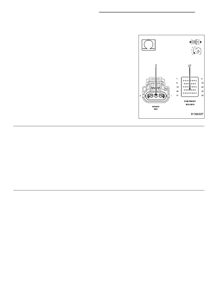
RESISTANCE IN THE (K900) SENSOR GROUND CIRCUIT
Measure the resistance of the (K900) Sensor ground circuit from the
MAP Sensor harness connector to the appropriate terminal of special
tool #8815.
Is the resistance below 5.0 ohms?
Yes
>> Go To 17
No
>> Repair the excessive resistance in the (K900) Sensor
ground circuit.
Perform the POWERTRAIN VERIFICATION TEST. (Refer
to 9 - ENGINE - STANDARD PROCEDURE)
17.
PCM
NOTE: Before continuing, check the PCM harness connector terminals for corrosion, damage, or terminal
push out. Repair as necessary.
Using the schematics as a guide, inspect the wire harness and connectors. Pay particular attention to all Power and
Ground circuits.
Were there any problems found?
Yes
>> Repair as necessary.
Perform the POWERTRAIN VERIFICATION TEST. (Refer to 9 - ENGINE - STANDARD PROCEDURE)
No
>> Replace and program the Powertrain Control Module per Service Information.
Perform the POWERTRAIN VERIFICATION TEST. (Refer to 9 - ENGINE - STANDARD PROCEDURE)
9 - 972
ENGINE ELECTRICAL DIAGNOSTICS
WK