Jeep Grand Cherokee WK. Manual - part 1034


  Index      Jeep     Jeep Grand Cherokee WK - service repair manual 2005 year


Search            


Content   ..  1032  1033  1034  1035   ..


Jeep Grand Cherokee WK. Manual - part 1034


P0653-SENSOR REFERENCE VOLTAGE 2 CIRCUIT HIGH (CONTINUED)

For the Engine circuit diagram (Refer to 9 - ENGINE - SCHEMATICS AND DIAGRAMS).

For a complete wiring diagram Refer to Section 8W.

When Monitored:
Ignition on.

Set Condition:
When the PCM recognizes the Auxiliary 5-volt Supply circuit voltage is too high. One Trip Fault. ETC light is
flashing.

Possible Causes

(F856) AUXILIARY 5-VOLT SUPPLY SHORTED TO BATTERY VOLTAGE

PCM

Always perform the Pre-Diagnostic Troubleshooting procedure before proceeding. (Refer to 9 - ENGINE -
DIAGNOSIS AND TESTING).

Diagnostic Test

1.

ACTIVE DTC

Ignition on, engine not running.

With a scan tool, read DTCs.

Is the DTC active at this time?

Yes

>> Go To 2

No

>> Refer to the INTERMITTENT CONDITION Diagnostic Procedure.

Perform the POWERTRAIN VERIFICATION TEST. (Refer to 9 - ENGINE - STANDARD PROCEDURE)

2.

(F856) AUXILIARY 5-VOLT SUPPLY SHORTED TO BATTERY VOLTAGE

Turn the ignition off.

Disconnect the C1 PCM harness connector.

Disconnect all the Sensors that share the (F856) Auxiliary 5-volt Sup-
ply circuit.

NOTE: Improperly installed aftermarket accessories can cause
this DTC to set. Check for wiring added by customer.
Ignition on, engine not running.

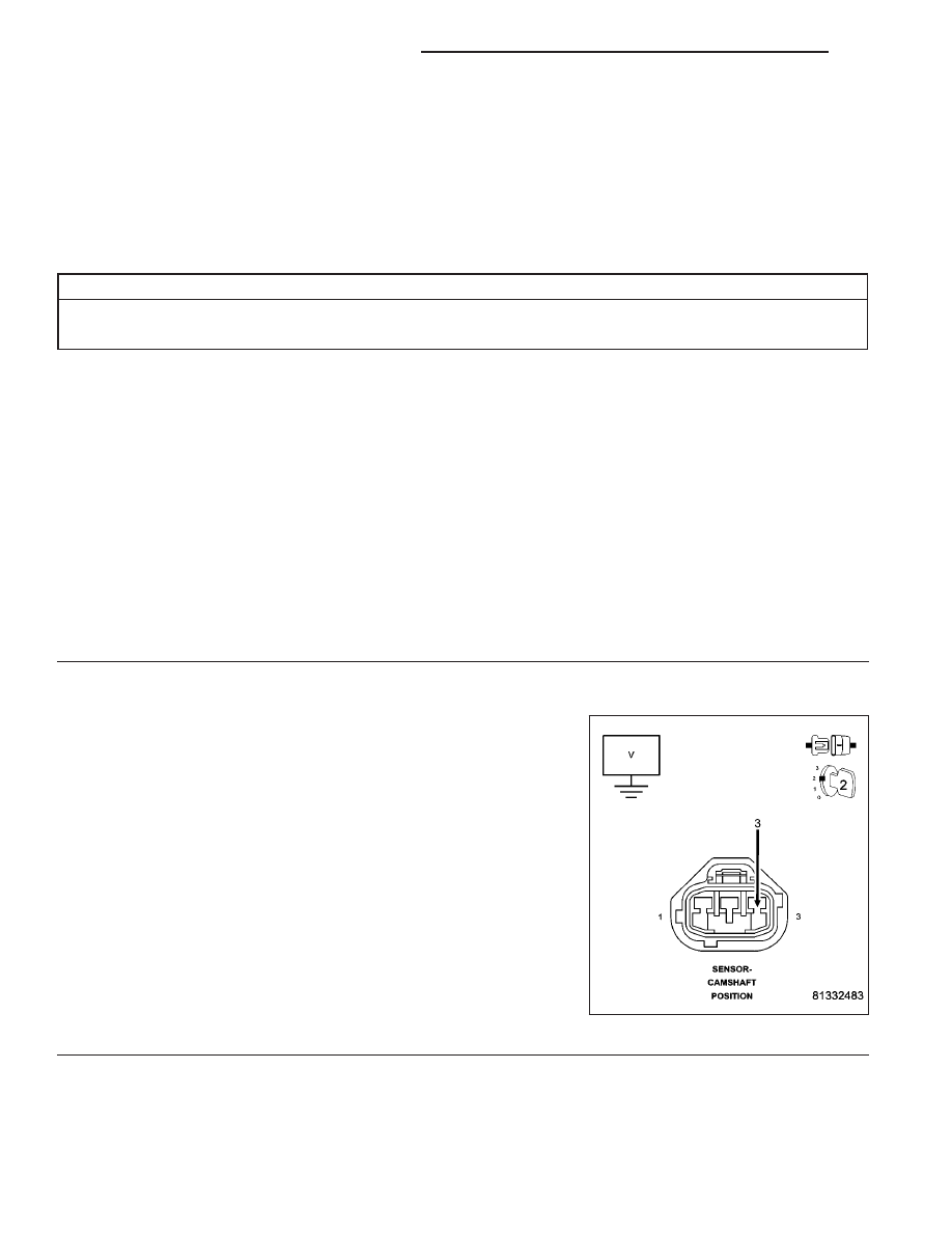
Measure the voltage on the (F856) Auxiliary 5-volt Supply circuit at the
CMP Sensor harness connector.

Is the voltage above 0 volts?

Yes

>> Repair the short to battery voltage in the (F856) Auxiliary

5-volt Supply circuit.

Perform the POWERTRAIN VERIFICATION TEST. (Refer
to 9 - ENGINE - STANDARD PROCEDURE)

No

>> Go To 3

9 - 732

ENGINE ELECTRICAL DIAGNOSTICS

WK

P0653-SENSOR REFERENCE VOLTAGE 2 CIRCUIT HIGH (CONTINUED)

3.

PCM

NOTE: Before continuing, check the PCM harness connector terminals for corrosion, damage, or terminal
push out. Repair as necessary.
Using the schematics as a guide, inspect the wire harness and connectors. Pay particular attention to all Power and
Ground circuits.

Were there any problems found?

Yes

>> Repair as necessary.

Perform the POWERTRAIN VERIFICATION TEST. (Refer to 9 - ENGINE - STANDARD PROCEDURE)

No

>> Replace and program the Powertrain Control Module per Service Information.

Perform the POWERTRAIN VERIFICATION TEST. (Refer to 9 - ENGINE - STANDARD PROCEDURE)

WK

ENGINE ELECTRICAL DIAGNOSTICS

9 - 733

P0685-AUTO SHUTDOWN RELAY CONTROL CIRCUIT

9 - 734

ENGINE ELECTRICAL DIAGNOSTICS

WK

P0685-AUTO SHUTDOWN RELAY CONTROL CIRCUIT (CONTINUED)

For the Engine circuit diagram (Refer to 9 - ENGINE - SCHEMATICS AND DIAGRAMS).

For a complete wiring diagram Refer to Section 8W.

When Monitored:
With ignition on. Battery voltage above 10 volts.

Set Condition:
The actual ASD state is not equal to the desired ASD state. One Trip Fault. Three good trips to turn off the
MIL.

Possible Causes

(A924) FUSED B+ CIRCUITS

(K342) ASD RELAY CONTROL CIRCUIT OPEN

(K342) ASD RELAY CONTROL CIRCUIT SHORTED TO GROUND

ASD RELAY

PCM

Always perform the Pre-Diagnostic Troubleshooting procedure before proceeding. (Refer to 9 - ENGINE -
DIAGNOSIS AND TESTING).

Diagnostic Test

1.

ASD RELAY OPERATION

Ignition on, engine not running.

With a scan tool, actuate the ASD Relay.

Is the ASD Relay operating?

Yes

>> Refer to the INTERMITTENT CONDITION Diagnostic Procedure.

Perform the POWERTRAIN VERIFICATION TEST. (Refer to 9 - ENGINE - STANDARD PROCEDURE)

No

>> Go To 2

2.

(A924) FUSED B+ CIRCUITS

Turn the ignition off.

Remove the ASD Relay from the IPM.

Using a 12-volt test light connected to ground, probe the (A924) Fused B+ circuits in the IPM.

Does the test light illuminate brightly?

Yes

>> Go To 3

No

>> Repair the open or short to ground in the (A924) Fused B+ circuits. Inspect and replace any open fuses.

Perform the POWERTRAIN VERIFICATION TEST. (Refer to 9 - ENGINE - STANDARD PROCEDURE)

3.

ASD RELAY

Measure the resistance of the ASD Relay Coil.

Is the resistance between 60 to 80 ohms?

Yes

>> Go To 4

No

>> Replace the ASD Relay.

Perform the POWERTRAIN VERIFICATION TEST. (Refer to 9 - ENGINE - STANDARD PROCEDURE)

WK

ENGINE ELECTRICAL DIAGNOSTICS

9 - 735


Content   ..  1032  1033  1034  1035   ..