Content .. 1030 1031 1032 1033 ..
Jeep Grand Cherokee WK. Manual - part 1032
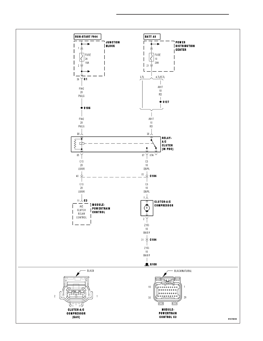
P0645-A/C CLUTCH RELAY CIRCUIT
9 - 724
ENGINE ELECTRICAL DIAGNOSTICS
WK
|
|
|
Content .. 1030 1031 1032 1033 ..
P0645-A/C CLUTCH RELAY CIRCUIT 9 - 724 ENGINE ELECTRICAL DIAGNOSTICS WK |