Jeep Grand Cherokee WK. Manual - part 1016


  Index      Jeep     Jeep Grand Cherokee WK - service repair manual 2005 year


Search            


Content   ..  1014  1015  1016  1017   ..


Jeep Grand Cherokee WK. Manual - part 1016


P0585-SPEED CONTROL SWITCH 1/2 CORRELATION (CONTINUED)

9.

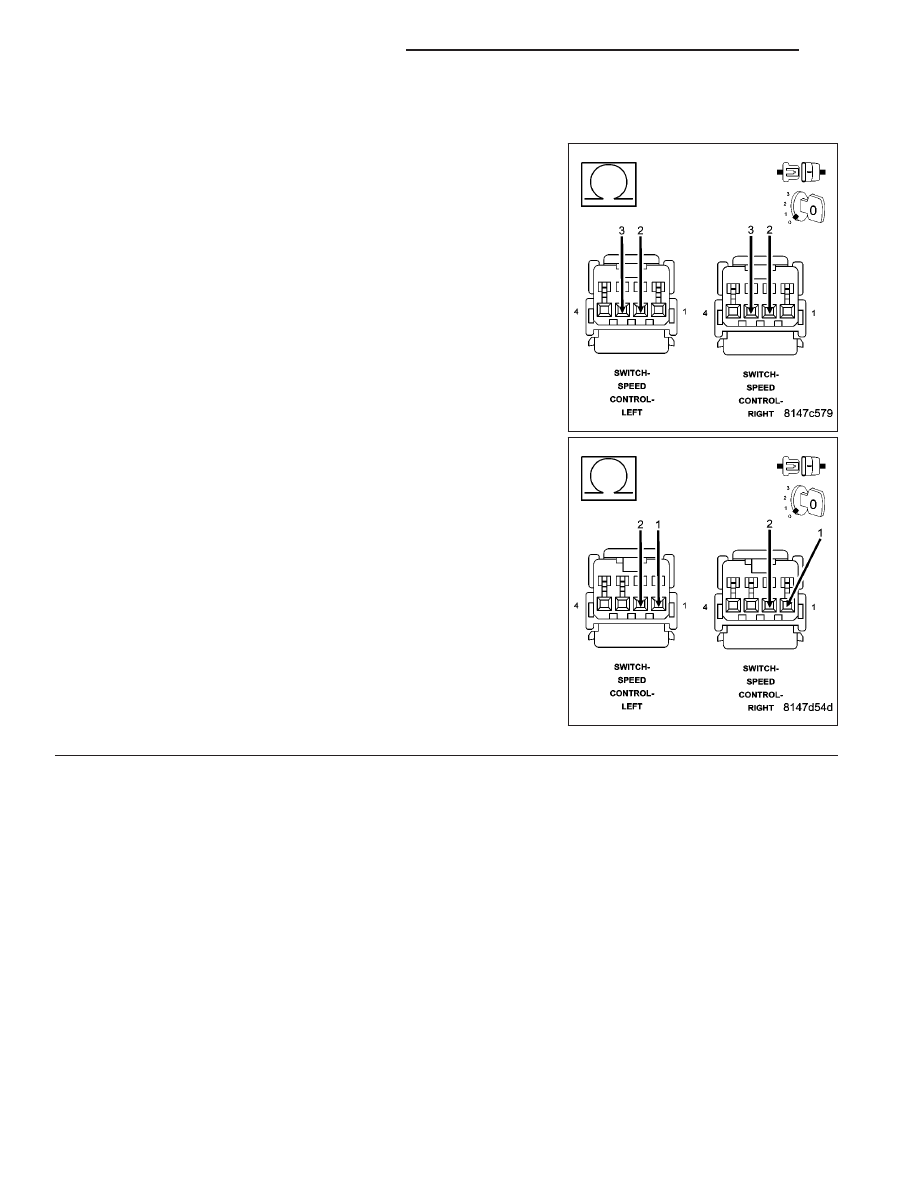
S/C SWITCH SIGNAL CIRCUITS SHORTED TO THE (V397/V937) SWITCH RETURN CIRCUIT

Measure the resistance between the (V397) Switch Return circuit and
both of the (V371) and (V372) S/C Switch Signal circuits in the S/C
Switch harness connector.

Is the resistance below 5.0 ohms?

Yes

>> Repair the short between the (V397/V937) Switch Return

circuit and the (V371/V71) or (V372/V72) S/C Switch Sig-
nal circuit.

Perform the POWERTRAIN VERIFICATION TEST. (Refer
to 9 - ENGINE - STANDARD PROCEDURE)

No

>> Go To 10

9 - 660

ENGINE ELECTRICAL DIAGNOSTICS

WK

P0585-SPEED CONTROL SWITCH 1/2 CORRELATION (CONTINUED)

10.

(V371/V71) S/C SWITCH NO.1 SIGNAL CIRCUIT SHORTED TO THE (V372/V72) S/C SWITCH NO.2
SIGNAL CIRCUIT

Measure the resistance between the (V371/V71) S/C Switch No.1 Sig-
nal circuit and the (V372/72) S/C Switch No.2 Signal circuit at both
Speed Control harness connectors.

Is the resistance below 100 ohms for each circuit?

Yes

>> Repair the short between the (V372/V72) S/C Switch No.2

Signal circuit and the (V371) S/C Switch No.1 Signal cir-
cuit.

Perform the POWERTRAIN VERIFICATION TEST. (Refer
to 9 - ENGINE - STANDARD PROCEDURE)

No

>> Go To 11

11.

S/C SWITCH SIGNAL CIRCUITS SHORTED TO GROUND

Measure the resistance between ground and the (V371/V71) and
(V372/V72) S/C Switch Signal circuits at both S/C Switch harness con-
nectors.

Is the resistance below 100 ohms?

Yes

>> Repair the short to ground in the (V371/V71) or (V372/

V72) S/C Switch Signal circuit.

Perform the POWERTRAIN VERIFICATION TEST. (Refer
to 9 - ENGINE - STANDARD PROCEDURE)

No

>> Go To 12

WK

ENGINE ELECTRICAL DIAGNOSTICS

9 - 661

P0585-SPEED CONTROL SWITCH 1/2 CORRELATION (CONTINUED)

12.

SPEED CONTROL SWITCH VOLTAGE VALUES

Allow the engine to idle.

With a scan tool, monitor the S/C Switch voltage readings.

SWITCH POSITION

SWITCH No.1 VOLTAGE VALUE

SWITCH No.2 VOLATGE VALUE

NO SWITCHES PRESSED

4.31 to 4.78 volts

4.31 to 4.78 volts

ON/OFF PRESSED

0.59 to 1.13 volts

3.53 to 3.92 volts

RES/ACCEL PRESSED

3.88 to 4.17 volts

2.04 to 2.47 volts

SET PRESSED

3.16 to 3.56 volts

1.17 to 1.56 volts

COAST PRESSED

2.57 to 2.94 volts

0.77 to 1.09 volts

CANCEL PRESSED

1.59 to 1.99 volts

2.84 to 3.25 volts

Take these same voltage measurements with a voltmeter by back probing the (V371) S/C Switch No.1 Signal circuit
and the (V372) S/C Switch No.2 Signal circuit at the switches.

Compare the voltage readings on the voltmeter to what the scan tool displayed.

Are the voltage readings out of the listed specification and is there less than a 0.2 of a volt difference
between the voltmeter switch values and the scan tool switch values?

Yes

>> Replace the Speed Control Switch.

Perform the POWERTRAIN VERIFICATION TEST. (Refer to 9 - ENGINE - STANDARD PROCEDURE)

No

>> Go To 13

13.

PCM

NOTE: Before continuing, check the PCM harness connector terminals for corrosion, damage, or terminal
push out. Repair as necessary.
Using the schematics as a guide, inspect the wire harness and connectors. Pay particular attention to all Power and
Ground circuits.

Were there any problems found?

Yes

>> Repair as necessary.

Perform the POWERTRAIN VERIFICATION TEST. (Refer to 9 - ENGINE - STANDARD PROCEDURE)

No

>> Replace and program the Powertrain Control Module per Service Information.

Perform the POWERTRAIN VERIFICATION TEST. (Refer to 9 - ENGINE - STANDARD PROCEDURE)

9 - 662

ENGINE ELECTRICAL DIAGNOSTICS

WK

P0586-SPEED CONTROL VENT CONTROL CIRCUIT

For the Engine circuit diagram (Refer to 9 - ENGINE - SCHEMATICS AND DIAGRAMS).

For a complete wiring diagram Refer to Section 8W.

When Monitored:
Ignition on and battery voltage greater than 10 volts.

Set Condition:
An open or shorted condition detected in the Speed control vent solenoid control circuit. One Trip Fault. Three
good trips to turn off the MIL.

Possible Causes

(V32) S/C SUPPLY CIRCUIT OPEN

(V32) S/C SUPPLY SHORT TO GROUND

(V35) S/C VENT SOL CONTROL CIRCUIT SHORTED TO GROUND

(V35) S/C VENT SOL CONTROL CIRCUIT OPEN

(Z384) GROUND CIRCUIT OPEN

SPEED CONTROL VENT SOLENOID

PCM

Always perform the Pre-Diagnostic Troubleshooting procedure before proceeding. (Refer to 9 - ENGINE -
DIAGNOSIS AND TESTING).

Diagnostic Test

1.

SPEED CONTROL VENT CONTROL

Ignition on, engine not running.

With the scan tool, read DTCs and record the related Freeze Frame data.

With the scan tool, actuate the Speed Control Vent Solenoid and note operation.

Does the Speed Control Vacuum Solenoid actuate properly?

Yes

>> Refer to the INTERMITTENT CONDITION symptom in the Driveability category.

Perform the POWERTRAIN VERIFICATION TEST. (Refer to 9 - ENGINE - STANDARD PROCEDURE)

No

>> Go To 2

WK

ENGINE ELECTRICAL DIAGNOSTICS

9 - 663


Content   ..  1014  1015  1016  1017   ..