Content .. 1009 1010 1011 1012 ..
Jeep Grand Cherokee WK. Manual - part 1011
P0580-SPEED CONTROL SWITCH 1 CIRCUIT LOW (CONTINUED)
10.
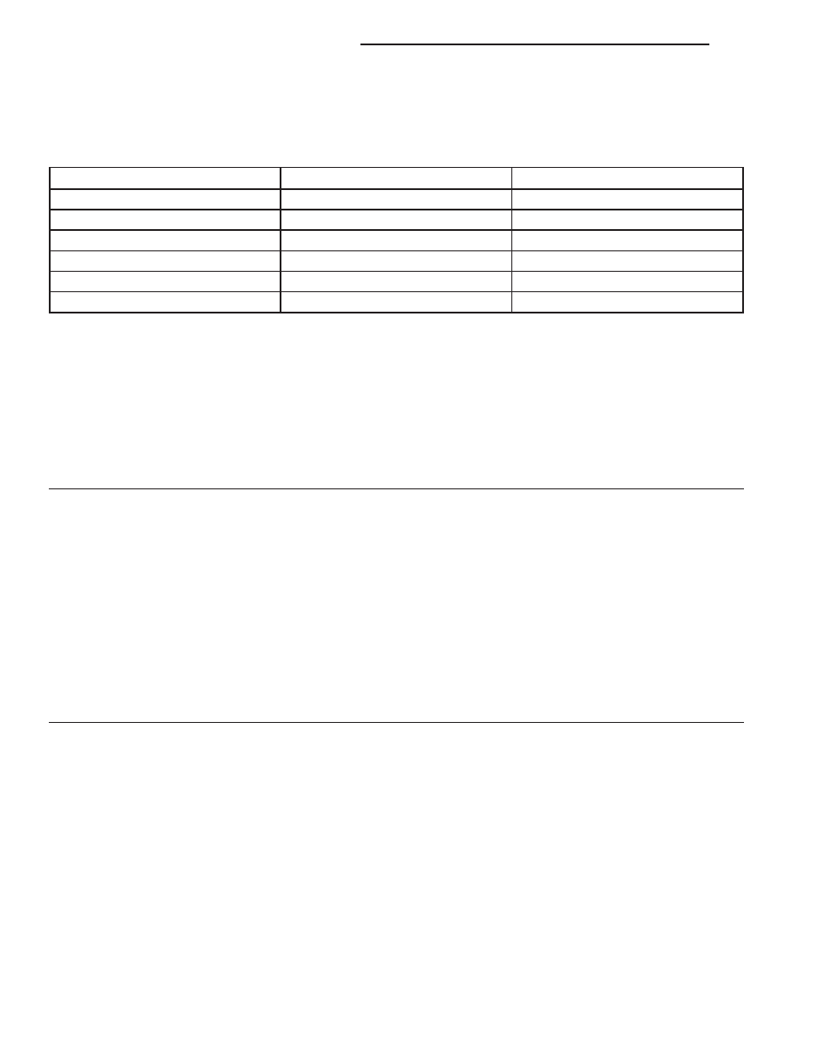
SPEED CONTROL SWITCH VOLTAGE VALUES
Allow the engine to idle.
With a scan tool, monitor the S/C Switch voltage readings.
SWITCH POSITION
SWITCH No.1 VOLTAGE VALUE
SWITCH No.2 VOLATGE VALUE
NO SWITCHES PRESSED
4.31 to 4.78 volts
4.31 to 4.78 volts
ON/OFF PRESSED
0.59 to 1.13 volts
3.53 to 3.92 volts
RES/ACCEL PRESSED
3.88 to 4.17 volts
2.04 to 2.47 volts
SET PRESSED
3.16 to 3.56 volts
1.17 to 1.56 volts
COAST PRESSED
2.57 to 2.94 volts
0.77 to 1.09 volts
CANCEL PRESSED
1.59 to 1.99 volts
2.84 to 3.25 volts
Take these same voltage measurements with a voltmeter by back probing the (V371) S/C Switch No.1 Signal circuit
at the switches.
Compare the voltage readings on the voltmeter to what the scan tool displayed.
Are the voltage readings out of the listed specification and is there less than a 0.2 of a volt difference
between the voltmeter switch values and the scan tool switch value?
Yes
>> Replace the Speed Control Switch.
Perform the POWERTRAIN VERIFICATION TEST. (Refer to 9 - ENGINE - STANDARD PROCEDURE)
No
>> Go To 11
11.
PCM
NOTE: Before continuing, check the PCM harness connector terminals for corrosion, damage, or terminal
push out. Repair as necessary.
Using the schematics as a guide, inspect the wire harness and connectors. Pay particular attention to all Power and
Ground circuits.
Were there any problems found?
Yes
>> Repair as necessary.
Perform the POWERTRAIN VERIFICATION TEST. (Refer to 9 - ENGINE - STANDARD PROCEDURE)
No
>> Replace and program the Powertrain Control Module per Service Information.
Perform the POWERTRAIN VERIFICATION TEST. (Refer to 9 - ENGINE - STANDARD PROCEDURE)
9 - 640
ENGINE ELECTRICAL DIAGNOSTICS
WK