Jeep Grand Cherokee WK. Manual - part 69
13. Install speed sensors (2) in axle tube (1) flange.
14. Install calipers and rotors.
15. Install differential cover, fill differential and install
fill plug.
ADJUSTMENTS
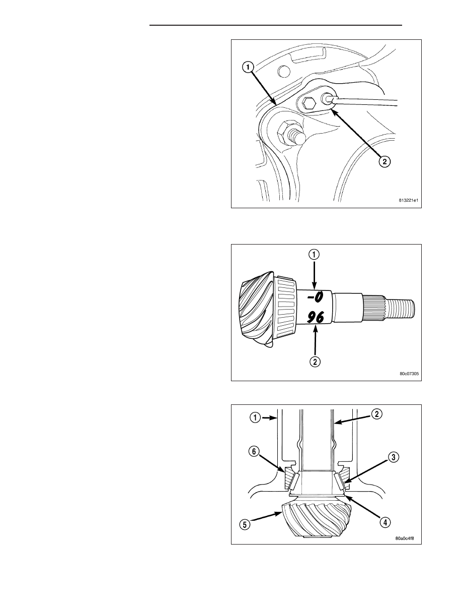
Ring gear and pinion are supplied as matched sets.
Identifying numbers for the ring gear and pinion are
painted onto the pinion gear shaft and the side of the
ring gear. A plus (+) number, minus (–) number or zero
(0) along with the gear set sequence number (2) (01
to 99) is on each gear. This first number (1) the
amount (in thousandths of an inch) the depth varies
from the standard depth setting of a pinion marked
with a (0). The next two numbers are the sequence
number of the gear set. The standard depth provides
the best teeth contact pattern.
Compensation for pinion depth variance is achieved
with select shims (4). The shims are placed behind the
rear pinion bearing.
If installing a new gear, note the depth variance num-
ber of the original and replacement pinion. Add or sub-
tract this number from the original depth shim/oil
slinger to compensate for the difference in the depth
variances. The numbers represent thousands of an
inch deviation from the standard. If the number is neg-
ative, add that value to the required thickness of the
depth shims. If the number is positive, subtract that
value from the thickness of the depth shim.
Pinion Gear Depth Variance Chart: Note where Old and New Pinion Marking columns intersect. Intersecting figure
represents plus or minus the amount needed.
3 - 174
REAR AXLE - C213R
WK