Jeep Grand Cherokee WJ. Manual - part 925


  Index      Jeep     Jeep Grand Cherokee WJ - service repair manual 2001 year


Search            


Content   ..  923  924  925  926   ..


Jeep Grand Cherokee WJ. Manual - part 925


THROTTLE PRESSURE ADJUSTMENT

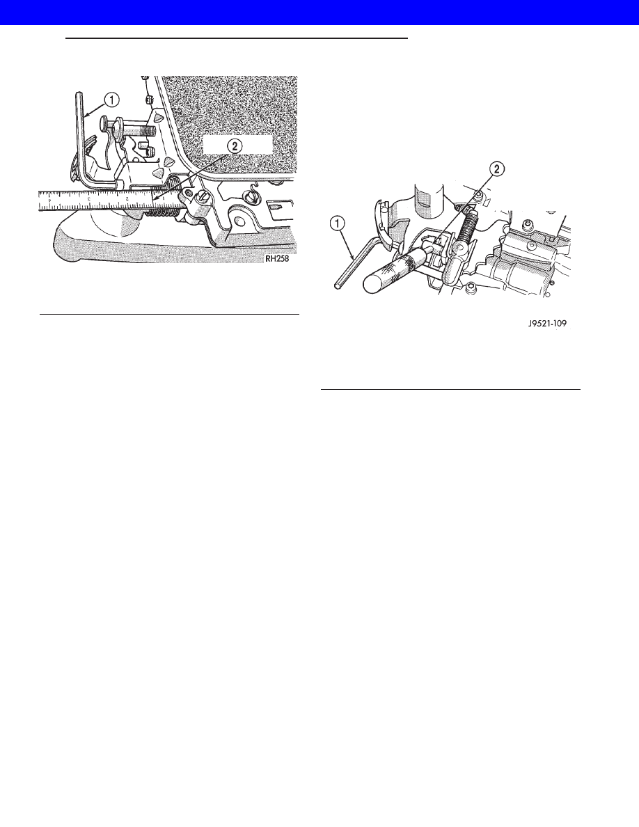
Insert Gauge Tool C-3763 between the throttle

lever cam and the kickdown valve stem (Fig. 324).

Push the gauge tool inward to compress the kick-

down valve against the spring and bottom the throt-
tle valve.

Maintain pressure against kickdown valve spring.

Turn throttle lever stop screw until the screw head

touches throttle lever tang and the throttle lever cam
touches gauge tool.

NOTE: The kickdown valve spring must be fully
compressed and the kickdown valve completely
bottomed to obtain correct adjustment.

Fig. 323 Line Pressure Adjustment

1 - WRENCH
2 - 1–5/16 INCH

Fig. 324 Throttle Pressure Adjustment

1 - HEX WRENCH (IN THROTTLE LEVER ADJUSTING SCREW)
2 - SPECIAL TOOL C-3763 (POSITIONED BETWEEN THROTTLE
LEVER AND KICKDOWN VALVE)

WG

AUTOMATIC - 44RE

21s - 207

VALVE BODY (Continued)

2001 JEEP GRAND CHEROKEE

AUTOMATIC-545RFE

TABLE OF CONTENTS

page

page

AUTOMATIC-545RFE

DESCRIPTION . . . . . . . . . . . . . . . . . . . . . . . . . . 208
DIAGNOSIS AND TESTING . . . . . . . . . . . . . . . . 208

AUTOMATIC TRANSMISSION. . . . . . . . . . . . . 208
ROAD TESTING . . . . . . . . . . . . . . . . . . . . . . . 209
HYDRAULIC PRESSURE TEST . . . . . . . . . . . 210
AIR CHECKING TRANSMISSION CLUTCH
OPERATION . . . . . . . . . . . . . . . . . . . . . . . . . . 211
CONVERTER HOUSING FLUID LEAK. . . . . . . 211

STANDARD PROCEDURE . . . . . . . . . . . . . . . . . 212

OIL PUMP VOLUME CHECK. . . . . . . . . . . . . . 212

DISASSEMBLY . . . . . . . . . . . . . . . . . . . . . . . . . . 212

ASSEMBLY . . . . . . . . . . . . . . . . . . . . . . . . . . . . 218
SCHEMATICS AND DIAGRAMS . . . . . . . . . . . . . 226
SPECIFICATIONS. . . . . . . . . . . . . . . . . . . . . . . . 247

INPUT CLUTCH ASSEMBLY

DESCRIPTION . . . . . . . . . . . . . . . . . . . . . . . . . . 248
OPERATION. . . . . . . . . . . . . . . . . . . . . . . . . . . . 248
DISASSEMBLY . . . . . . . . . . . . . . . . . . . . . . . . . . 249
ASSEMBLY . . . . . . . . . . . . . . . . . . . . . . . . . . . . 251

OVERDRIVE SWITCH

DESCRIPTION . . . . . . . . . . . . . . . . . . . . . . . . . . 257
OPERATION. . . . . . . . . . . . . . . . . . . . . . . . . . . . 257

AUTOMATIC-545RFE

DESCRIPTION

The 545RFE automatic transmission is a sophisti-

cated, multi-range, electronically controlled transmis-
sion

which

combines

optimized

gear

ratios

for

responsive performance, state of the art efficiency
features and low NVH. Other features include driver
adaptive shifting and three planetary gear sets to
provide wide ratio capability with precise ratio steps
for optimum driveability. The three planetary gear
sets also make available a unique alternate second
gear ratio. The primary 2nd gear ratio fits between
1st and 3rd gears for normal through-gear accelera-
tions. The alternate second gear ratio (2prime) allows
smoother 4-2 kickdowns at high speeds to provide
2nd gear passing performance over a wider highway
cruising range. An additional overdrive ratio (0.67:1)
is also provided for greater fuel economy and less
NVH at highway speeds.

The hydraulic portion of the transmission consists

of the transmission fluid, fluid passages, hydraulic
valves, and various line pressure control components.

The primary mechanical components of the trans-

mission consist of the following:

• Three multiple disc input clutches

• Three multiple disc holding clutches

• Five hydraulic accumulators

• Three planetary gear sets

• Dual Stage Hydraulic oil pump

• Valve body

• Solenoid pack

The TCM is the “heart” or “brain” of the electronic

control system and relies on information from vari-
ous direct and indirect inputs (sensors, switches, etc.)
to determine driver demand and vehicle operating
conditions. With this information, the TCM can cal-
culate and perform timely and quality shifts through
various output or control devices (solenoid pack,
transmission control relay, etc.).

TRANSMISSION IDENTIFICATION

Transmission identification numbers are stamped

on the left side of the case just above the oil pan
sealing surface (Fig. 1). Refer to this information
when ordering replacement parts. A label is attached
to the transmission case above the stamped numbers.
The label gives additional information which may
also be necessary for identification purposes.

GEAR RATIOS The 545RFE gear ratios are:

1st . . . . . . . . . . . . . . . . . . . . . . . . . . . . . . . . . 3.00:1
2nd . . . . . . . . . . . . . . . . . . . . . . . . . . . . . . . . . 1.67:1
2nd Prime . . . . . . . . . . . . . . . . . . . . . . . . . . . . 1.50:1
3rd . . . . . . . . . . . . . . . . . . . . . . . . . . . . . . . . . 1.00:1
4th . . . . . . . . . . . . . . . . . . . . . . . . . . . . . . . . . 0.75:1
5th . . . . . . . . . . . . . . . . . . . . . . . . . . . . . . . . . 0.67:1
Reverse . . . . . . . . . . . . . . . . . . . . . . . . . . . . . . 3.00:1

DIAGNOSIS AND TESTING - AUTOMATIC
TRANSMISSION

CAUTION:

Before

attempting

any

repair

on

a

545RFE automatic transmission, check for Diagnos-
tic Trouble Codes with the DRB

T

scan tool.

21s - 208

AUTOMATIC-545RFE

WG

2001 JEEP GRAND CHEROKEE

Transmission malfunctions may be caused by these

general conditions:

• Poor engine performance

• Improper adjustments

• Hydraulic malfunctions

• Mechanical malfunctions

• Electronic malfunctions
Diagnosis of these problems should always begin

by checking the easily accessible variables: fluid level
and condition, gearshift cable adjustment. Then per-
form a road test to determine if the problem has been
corrected or if more diagnosis is necessary. If the
problem persists after the preliminary tests and cor-
rections are completed, hydraulic pressure checks
should be performed.

DIAGNOSIS AND TESTING - ROAD TESTING

Before road testing, be sure the fluid level and con-

trol

cable

adjustments

have

been

checked

and

adjusted if necessary. Verify that all diagnostic trou-
ble codes have been resolved.

Observe engine performance during the road test.

A poorly tuned engine will not allow accurate analy-
sis of transmission operation.

Operate the transmission in all gear ranges. Check

for shift variations and engine flare which indicates
slippage. Note if shifts are harsh, spongy, delayed,
early, or if part throttle downshifts are sensitive.

Slippage indicated by engine flare, usually means

clutch, overrunning clutch, or line presure problems.

A slipping clutch can often be determined by com-

paring which internal units are applied in the vari-
ous gear ranges. The Clutch Application chart
provides a basis for analyzing road test results.

CLUTCH APPLICATION CHART

SLP

UD

OD

R

2C

4C

L/R

OVERRUNNING

P–PARK

ON

R–REVERSE

ON

ON

N-NEUTRAL

ON

D–OVERDRIVE

FIRST

ON

ON*

ON

SECOND

ON

ON

SECOND PRIME

ON

ON

THIRD

ON

ON

FOURTH

ON

ON

FIFTH

ON

ON

LIMP-IN

ON

ON

2–FIRST

ON

ON*

ON

SECOND

ON

ON

LIMP-IN

ON

ON

1–LOW

ON

ON

ON

*L/R clutch is on only with the output shaft speed below 150 rpm.

Fig. 1 Transmission Part And Serial Number

Location

1 - IDENTIFICATION NUMBERS (STAMPED)

WG

AUTOMATIC-545RFE

21s - 209

AUTOMATIC-545RFE (Continued)

2001 JEEP GRAND CHEROKEE

DIAGNOSIS AND TESTING - HYDRAULIC
PRESSURE TEST

An accurate tachometer and pressure test gauges

are required. Test Gauge C-3293-SP has a 300 psi
range and is used at all locations where pressures
exceed 100 psi.

Pressure Test Port Locations

Only two pressure ports are supplied on the trans-

mission case. The torque converter clutch apply and
release ports are located on the right side of the
transmission case (Fig. 2).

To determine the line pressure, there are two avail-

able methods. The DRB

t scan tool can be used to

read line pressure from the line pressure sensor. The
second method is to install Line Pressure Adapter
8259 (Fig. 4) into the transmission case and then
install the pressure gauge and the original sensor
into the adapter. This will allow a comparison of the
DRB

t readings and the gauge reading to determe the

accuracy of the line pressure sensor. The DRB

t line

pressure reading should match the gauge reading
within ±10 psi.

In order to access any other pressure tap locations,

the transmission oil pan must be removed, the pres-
sure port plugs removed and Valve Body Pressure
Tap Adapter 8258-A (Fig. 5) installed. The extensions
supplied with Adapter 8258-A will allow the installa-
tion of pressure gauges to the valve body. Refer to
(Fig. 3) for correct pressure tap location identifica-
tion.

TEST PROCEDURE

All pressure readings should be taken with the

transmission fluid level full, transmission oil at the
normal operating temperature, and the engine at
1500 rpm. Check the transmission for proper opera-
tion in each gear position that is in question or if a
specific element is in question, check the pressure
readings in at least two gear positions that employ
that element. Refer to the Hydraulic Schematics at
the rear of this section to determine the correct pres-
sures for each element in a given gear position.

Fig. 2 Torque Converter Pressure Locations

1 - TCC RELEASE
2 - TO COOLER
3 - TCC APPLY
4 - FROM COOLER
5 - LINE PRESSURE SENSOR

Fig. 3 Pressure Tap Locations

Fig. 4 Line Pressure Adapter 8259

1 - LINE PRESSURE SENSOR PORT
2 - LINE PRESSURE SENSOR
3 - TOOL 8259
4 - PRESSURE TAP

21s - 210

AUTOMATIC-545RFE

WG

AUTOMATIC-545RFE (Continued)

2001 JEEP GRAND CHEROKEE


Content   ..  923  924  925  926   ..