Jeep Grand Cherokee WJ. Manual - part 916


  Index      Jeep     Jeep Grand Cherokee WJ - service repair manual 2001 year


Search            


Content   ..  914  915  916  917   ..


Jeep Grand Cherokee WJ. Manual - part 916


TURBINE

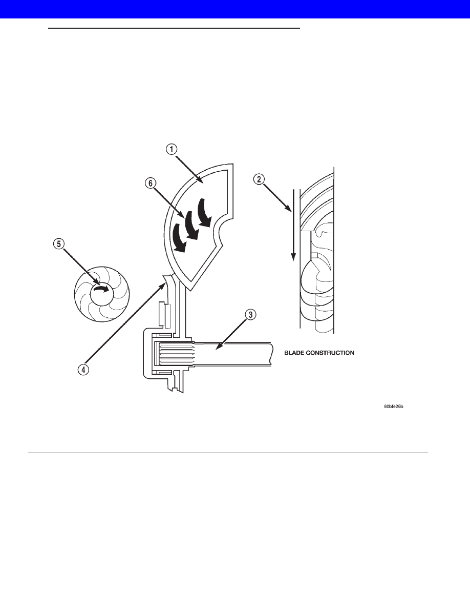
The turbine (Fig. 252) is the output, or driven,

member of the converter. The turbine is mounted
within the housing opposite the impeller, but is not
attached to the housing. The input shaft is inserted
through the center of the impeller and splined into
the turbine. The design of the turbine is similar to
the impeller, except the blades of the turbine are
curved in the opposite direction.

Fig. 252 Turbine

1 - TURBINE VANE

4 - PORTION OF TORQUE CONVERTER COVER

2 - ENGINE ROTATION

5 - ENGINE ROTATION

3 - INPUT SHAFT

6 - OIL FLOW WITHIN TURBINE SECTION

WG

AUTOMATIC - 44RE

21s - 171

TORQUE CONVERTER (Continued)

2001 JEEP GRAND CHEROKEE

STATOR

The stator assembly (Fig. 253) is mounted on a sta-

tionary shaft which is an integral part of the oil
pump. The stator is located between the impeller and
turbine within the torque converter case (Fig. 254).
The stator contains an over-running clutch, which
allows the stator to rotate only in a clockwise direc-
tion. When the stator is locked against the over-run-
ning clutch, the torque multiplication feature of the
torque converter is operational.

TORQUE CONVERTER CLUTCH (TCC)

The TCC (Fig. 255) was installed to improve the

efficiency of the torque converter that is lost to the
slippage of the fluid coupling. Although the fluid cou-
pling provides smooth, shock-free power transfer, it is
natural for all fluid couplings to slip. If the impeller
and turbine were mechanically locked together, a
zero slippage condition could be obtained. A hydraulic
piston was added to the turbine, and a friction mate-
rial was added to the inside of the front cover to pro-
vide this mechanical lock-up.

OPERATION

The converter impeller (Fig. 256) (driving member),

which is integral to the converter housing and bolted
to the engine drive plate, rotates at engine speed.
The converter turbine (driven member), which reacts
from fluid pressure generated by the impeller, rotates
and turns the transmission input shaft.

Fig. 253 Stator Components

1 - CAM (OUTER RACE)
2 - ROLLER
3 - SPRING
4 - INNER RACE

Fig. 254 Stator Location

1 - STATOR
2 - IMPELLER
3 - FLUID FLOW
4 - TURBINE

Fig. 255 Torque Converter Clutch (TCC)

1 - IMPELLER FRONT COVER
2 - THRUST WASHER ASSEMBLY
3 - IMPELLER
4 - STATOR
5 - TURBINE
6 - PISTON
7 - FRICTION DISC

21s - 172

AUTOMATIC - 44RE

WG

TORQUE CONVERTER (Continued)

2001 JEEP GRAND CHEROKEE

TURBINE

As the fluid that was put into motion by the impel-

ler blades strikes the blades of the turbine, some of
the energy and rotational force is transferred into the
turbine and the input shaft. This causes both of them
(turbine and input shaft) to rotate in a clockwise
direction following the impeller. As the fluid is leav-
ing the trailing edges of the turbine’s blades it con-
tinues in a “hindering” direction back toward the
impeller. If the fluid is not redirected before it strikes
the impeller, it will strike the impeller in such a
direction that it would tend to slow it down.

STATOR

Torque multiplication is achieved by locking the

stator’s over-running clutch to its shaft (Fig. 257).
Under stall conditions (the turbine is stationary), the
oil leaving the turbine blades strikes the face of the
stator blades and tries to rotate them in a counter-
clockwise direction. When this happens the overrun-
ning clutch of the stator locks and holds the stator
from rotating. With the stator locked, the oil strikes
the stator blades and is redirected into a “helping”
direction before it enters the impeller. This circula-
tion of oil from impeller to turbine, turbine to stator,
and stator to impeller, can produce a maximum
torque multiplication of about 2.4:1. As the turbine
begins to match the speed of the impeller, the fluid

that was hitting the stator in such as way as to
cause it to lock-up is no longer doing so. In this con-
dition of operation, the stator begins to free wheel
and the converter acts as a fluid coupling.

Fig. 256 Torque Converter Fluid Operation

1 - APPLY PRESSURE

3 - RELEASE PRESSURE

2 - THE PISTON MOVES SLIGHTLY FORWARD

4 - THE PISTON MOVES SLIGHTLY REARWARD

Fig. 257 Stator Operation

1 - DIRECTION STATOR WILL FREE WHEEL DUE TO OIL
PUSHING ON BACKSIDE OF VANES
2 - FRONT OF ENGINE
3 - INCREASED ANGLE AS OIL STRIKES VANES
4 - DIRECTION STATOR IS LOCKED UP DUE TO OIL PUSHING
AGAINST STATOR VANES

WG

AUTOMATIC - 44RE

21s - 173

TORQUE CONVERTER (Continued)

2001 JEEP GRAND CHEROKEE

TORQUE CONVERTER CLUTCH (TCC)

The

torque

converter

clutch

is

hydraulically

applied and is released when fluid is vented from the
hydraulic circuit by the torque converter control
(TCC) solenoid on the valve body. The torque con-
verter clutch is controlled by the Powertrain Control
Module (PCM). The torque converter clutch engages
in fourth gear, and in third gear under various con-
ditions, such as when the O/D switch is OFF, when
the vehicle is cruising on a level surface after the
vehicle has warmed up. The torque converter clutch
will disengage momentarily when an increase in
engine load is sensed by the PCM, such as when the
vehicle begins to go uphill or the throttle pressure is
increased.

REMOVAL

(1) Remove transmission and torque converter

from vehicle.

(2) Place a suitable drain pan under the converter

housing end of the transmission.

CAUTION: Verify that transmission is secure on the
lifting device or work surface, the center of gravity
of the transmission will shift when the torque con-
verter is removed creating an unstable condition.
The torque converter is a heavy unit. Use caution
when separating the torque converter from the
transmission.

(3) Pull the torque converter forward until the cen-

ter hub clears the oil pump seal.

(4) Separate the torque converter from the trans-

mission.

INSTALLATION

Check converter hub and drive notches for sharp

edges, burrs, scratches, or nicks. Polish the hub and
notches with 320/400 grit paper or crocus cloth if nec-
essary. The hub must be smooth to avoid damaging
the pump seal at installation.

(1) Lubricate oil pump seal lip with transmission

fluid.

(2) Place torque converter in position on transmis-

sion.

CAUTION: Do not damage oil pump seal or bushing
while inserting torque converter into the front of the
transmission.

(3) Align torque converter to oil pump seal open-

ing.

(4) Insert torque converter hub into oil pump.
(5) While pushing torque converter inward, rotate

converter until converter is fully seated in the oil
pump gears.

(6) Check converter seating with a scale and

straightedge (Fig. 258). Surface of converter lugs
should be 1/2 in. to rear of straightedge when con-
verter is fully seated.

(7) If necessary, temporarily secure converter with

C-clamp attached to the converter housing.

(8) Install the transmission in the vehicle.
(9) Fill the transmission with the recommended

fluid.

Fig. 258 Checking Torque Converter Seating -

Typical

1 - SCALE
2 - STRAIGHTEDGE

21s - 174

AUTOMATIC - 44RE

WG

TORQUE CONVERTER (Continued)

2001 JEEP GRAND CHEROKEE


Content   ..  914  915  916  917   ..