Jeep Grand Cherokee WJ. Manual - part 915


  Index      Jeep     Jeep Grand Cherokee WJ - service repair manual 2001 year


Search            


Content   ..  913  914  915  916   ..


Jeep Grand Cherokee WJ. Manual - part 915


The most common practice is to increase the num-

ber of turns by using thin wire that can completely
fill the available space within the solenoid housing.
The strength of the spring and the length of the
plunger also contribute to the response speed possi-
ble by a particular solenoid design.

A solenoid can also be described by the method by

which it is controlled. Some of the possibilities
include variable force, pulse-width modulated, con-
stant ON, or duty cycle. The variable force and pulse-
width modulated versions utilize similar methods to
control the current flow through the solenoid to posi-
tion the solenoid plunger at a desired position some-
where between full ON and full OFF. The constant
ON and duty cycled versions control the voltage
across the solenoid to allow either full flow or no flow
through the solenoid’s valve.

OPERATION

When an electrical current is applied to the sole-

noid coil, a magnetic field is created which produces
an attraction to the plunger, causing the plunger to
move and work against the spring pressure and the
load applied by the fluid the valve is controlling. The
plunger is normally directly attached to the valve
which it is to operate. When the current is removed
from the coil, the attraction is removed and the
plunger will return to its original position due to
spring pressure.

The plunger is made of a conductive material and

accomplishes this movement by providing a path for
the magnetic field to flow. By keeping the air gap
between the plunger and the coil to the minimum
necessary to allow free movement of the plunger, the
magnetic field is maximized.

THROTTLE VALVE CABLE

DESCRIPTION

Transmission throttle valve cable adjustment is

extremely important to proper operation. This adjust-
ment positions the throttle valve, which controls shift
speed, quality, and part-throttle downshift sensitivity.

If cable setting is too loose, early shifts and slip-

page between shifts may occur. If the setting is too
tight, shifts may be delayed and part throttle down-
shifts may be very sensitive.

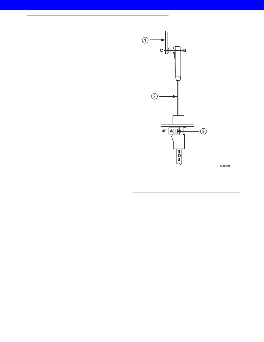
The transmission throttle valve is operated by a

cam on the throttle lever. The throttle lever is oper-
ated by an adjustable cable (Fig. 246). The cable is
attached to an arm mounted on the throttle lever
shaft. A retaining clip at the engine-end of the cable
is removed to provide for cable adjustment. The
retaining clip is then installed back onto the throttle
valve cable to lock in the adjustment.

ADJUSTMENTS - TRANSMISSION THROTTLE
VALVE CABLE

A correctly adjusted throttle valve cable will cause

the throttle lever on the transmission to move simul-
taneously with the throttle body lever from the idle
position. Proper adjustment will allow simultaneous
movement without causing the transmission throttle
lever to either move ahead of, or lag behind the lever
on the throttle body.

Checking Throttle Valve Cable Adjustment

(1) Turn ignition key to OFF position.
(2) Disconnect the negative battery cable.
(3) Remove air cleaner.
(4) Verify that lever on throttle body is at curb idle

position. Then verify that the transmission throttle
lever (Fig. 247) is also at idle (fully forward) position.

(5) Slide cable off attachment stud on throttle body

lever.

(6) Compare position of cable end to attachment

stud on throttle body lever:

Fig. 246 Throttle Valve Cable at Throttle Linkage

1 - THROTTLE LINKAGE
2 - THROTTLE VALVE CABLE LOCKING CLIP
3 - THROTTLE VALVE CABLE

WG

AUTOMATIC - 44RE

21s - 167

SOLENOID (Continued)

2001 JEEP GRAND CHEROKEE

• Cable end and attachment stud should be

aligned (or centered on one another) to within 1 mm
(0.039 in.) in either direction (Fig. 248).

• If cable end and attachment stud are misaligned

(off center), cable will have to be adjusted as
described in Throttle Valve Cable Adjustment proce-
dure.

(7) Reconnect cable end to attachment stud. Then

with aid of a helper, observe movement of transmis-
sion throttle lever and lever on throttle body.

• If both levers move simultaneously from idle to

half-throttle and back to idle position, adjustment is
correct.

• If transmission throttle lever moves ahead of, or

lags behind throttle body lever, cable adjustment will
be necessary. Or, if throttle body lever prevents
transmission lever from returning to closed position,
cable adjustment will be necessary.

Throttle Valve Cable Adjustment Procedure

(1) Turn ignition switch to OFF position.
(2) Remove air cleaner if necessary.
(3) Disconnect cable end from attachment stud.

Carefully slide cable off stud. Do not pry or pull
cable off.

(4) Verify that transmission throttle lever is in

fully closed position. Then be sure lever on throttle
body is at curb idle position.

(5) Pry the T.V. cable lock (A) into the UP position

(Fig. 248). This will unlock the cable and allow for
readjustment.

(6) Apply just enough tension on the T.V. cable (B)

to remove any slack in the braided cable.Pulling to
tight will cause the T.V. lever on the transmis-
sion to move out of its idle position, which will
result in an incorrect T.V. cable adjustment.
Slide the sheath of the T.V. cable (D) back and forth
until the centerlines of the T.V. cable end (B) and the
throttle bell crank lever (C) are aligned within one
millimeter (1mm) (Fig. 248).

(7) While holding the T.V. cable in the set position

push the T.V. cable lock (A) into the down position
(Fig. 248). This will lock the present T.V. cable
adjustment.

Fig. 247 Throttle Valve Cable at Transmission

1 - TRANSMISSION SHIFTER CABLE
2 - THROTTLE VALVE CABLE
3 - TRANSFER CASE SHIFTER CABLE
4 - TRANSFER CASE SHIFTER CABLE BRACKET RETAINING
BOLT (1 OR 2)
5 - THROTTLE VALVE CABLE BRACKET RETAINING BOLT
6 - ELECTRICAL CONNECTORS
7 - TRANSMISSION FLUID LINES

Fig. 248 Throttle Valve Cable at Throttle Linkage

1 - THROTTLE LINKAGE
2 - THROTTLE VALVE CABLE LOCKING CLIP
3 - THROTTLE VALVE CABLE

21s - 168

AUTOMATIC - 44RE

WG

THROTTLE VALVE CABLE (Continued)

2001 JEEP GRAND CHEROKEE

NOTE: Be sure that as the cable is pulled forward
and centered on the throttle lever stud, the cable
housing moves smoothly with the cable. Due to the
angle at which the cable housing enters the spring
housing, the cable housing may bind slightly and
create an incorrect adjustment.

(8) Reconnect the T.V. cable (B) to the throttle bell

crank lever (C).

(9) Check cable adjustment. Verify transmission

throttle lever and lever on throttle body move simul-
taneously.

(10) Connect the negative battery cable.

SPEED SENSOR

DESCRIPTION

The speed sensor (Fig. 249) is located in the over-

drive gear case. The sensor is positioned over the
park gear and monitors transmission output shaft
rotating speed.

OPERATION

Speed sensor signals are triggered by the park

gear lugs as they rotate past the sensor pickup face.
Input signals from the sensor are sent to the trans-
mission control module for processing. Signals from
this sensor are shared with the powertrain control
module.

TORQUE CONVERTER

DESCRIPTION

The torque converter (Fig. 250) is a hydraulic

device that couples the engine crankshaft to the
transmission. The torque converter consists of an
outer shell with an internal turbine, a stator, an
overrunning clutch, an impeller and an electronically
applied converter clutch. The converter clutch pro-

vides reduced engine speed and greater fuel economy
when engaged. Clutch engagement also provides
reduced transmission fluid temperatures. The torque
converter hub drives the transmission oil (fluid)
pump.

The torque converter is a sealed, welded unit that

is not repairable and is serviced as an assembly.

CAUTION: The torque converter must be replaced if
a transmission failure resulted in large amounts of
metal or fiber contamination in the fluid. If the fluid
is contaminated, flush the all transmission fluid
cooler(s) and lines.

Fig. 249 Transmission Output Speed Sensor

1 - TRANSMISSION OUTPUT SHAFT SPEED SENSOR
2 - SEAL

Fig. 250 Torque Converter Assembly

1 - TURBINE
2 - IMPELLER
3 - HUB
4 - STATOR
5 - FRONT COVER
6 - CONVERTER CLUTCH DISC
7 - DRIVE PLATE

WG

AUTOMATIC - 44RE

21s - 169

THROTTLE VALVE CABLE (Continued)

2001 JEEP GRAND CHEROKEE

IMPELLER

The impeller (Fig. 251) is an integral part of the

converter housing. The impeller consists of curved
blades placed radially along the inside of the housing
on the transmission side of the converter. As the con-
verter housing is rotated by the engine, so is the
impeller, because they are one and the same and are
the driving members of the system.

Fig. 251 Impeller

1 - ENGINE FLEXPLATE

4 - ENGINE ROTATION

2 - OIL FLOW FROM IMPELLER SECTION INTO TURBINE
SECTION

5 - ENGINE ROTATION

3 - IMPELLER VANES AND COVER ARE INTEGRAL

21s - 170

AUTOMATIC - 44RE

WG

TORQUE CONVERTER (Continued)

2001 JEEP GRAND CHEROKEE


Content   ..  913  914  915  916   ..