Jeep Grand Cherokee WJ. Manual - part 904


  Index      Jeep     Jeep Grand Cherokee WJ - service repair manual 2001 year


Search            


Content   ..  902  903  904  905   ..


Jeep Grand Cherokee WJ. Manual - part 904


OIL PUMP

DESCRIPTION

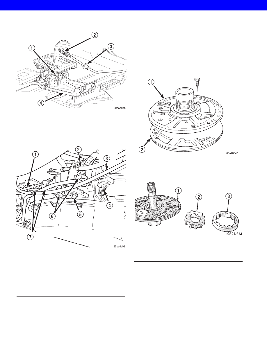
The oil pump (Fig. 117) is located in the pump

housing inside the bell housing of the transmission
case. The oil pump consists of an inner and outer
gear (Fig. 118), a housing, and a cover that also
serves as the reaction shaft support.

OPERATION

As the torque converter rotates, the converter hub

rotates the inner and outer gears. As the gears
rotate,

the

clearance

between

the

gear

teeth

increases in the crescent area, and creates a suction
at the inlet side of the pump. This suction draws
fluid through the pump inlet from the oil pan. As the
clearance between the gear teeth in the crescent area
decreases, it forces pressurized fluid into the pump
outlet and to the valve body.

Fig. 115 Shift Cable at the Shifter

1 - SHIFT LEVER PIN
2 - ADJUSTMENT SCREW
3 - SHIFT CABLE
4 - SHIFTER ASSEMBLY BRACKET

Fig. 116 Shift Cable at Transmission

1 - TRANSMISSION SHIFTER CABLE
2 - THROTTLE VALVE CABLE
3 - TRANSFER CASE SHIFTER CABLE
4 - TRANSFER CASE SHIFTER CABLE BRACKET RETAINING
BOLT(S)
5 - THROTTLE VALVE CABLE BRACKET RETAINING BOLT
6 - ELECTRICAL CONNECTORS
7 - TRANSMISSION FLUID LINES

Fig. 117 Oil Pump and Reaction Shaft Support

1 - REACTION SHAFT SUPPORT
2 - PUMP

Fig. 118 Pump Gear Removal

1 - REACTION SHAFT SUPPORT
2 - INNER GEAR
3 - OUTER GEAR

WG

AUTOMATIC - 44RE

21s - 123

GEAR SHIFT CABLE (Continued)

2001 JEEP GRAND CHEROKEE

STANDARD PROCEDURE - OIL PUMP VOLUME
CHECK

Measuring the oil pump output volume will deter-

mine if sufficient oil flow to the transmission oil
cooler exists, and whether or not an internal trans-
mission failure is present.

Verify that the transmission fluid is at the proper

level. Refer to the Fluid Level Check procedure in
this section. If necessary, fill the transmission to the
proper level with Mopar

t ATF +4, type 9602, Auto-

matic Transmission Fluid.

(1) Disconnect the To cooler line at the cooler

inlet and place a collecting container under the dis-
connected line.

CAUTION: With the fluid set at the proper level,
fluid collection should not exceed (1) quart or inter-
nal damage to the transmission may occur.

(2) Run the engine at curb idle speed, with the

shift selector in neutral.

(3) If one quart of transmission fluid is collected in

the container in 20 seconds or less, oil pump flow vol-
ume is within acceptable limits. If fluid flow is inter-
mittent, or it takes more than 20 seconds to collect
one quart of fluid, refer to the Hydraulic Pressure
tests in this section for further diagnosis.

(4) Re-connect the To cooler line to the transmis-

sion cooler inlet.

(5) Refill the transmission to proper level.

DISASSEMBLY

(1) Remove seal ring from housing and reaction

shaft support (Fig. 119).

(2) Mark pump housing and support assembly for

alignment reference.

(3) Remove bolts attaching pump body to support

(Fig. 120).

(4) Separate support from pump housing (Fig.

121).

(5) Remove inner and outer gears from reaction

shaft support (Fig. 122).

(6) If pump seal was not removed during transmis-

sion disassembly, remove seal with punch and ham-
mer.

(7) Remove front clutch thrust washer from sup-

port hub (Fig. 123).

OIL PUMP BUSHING REPLACEMENT

(1) Remove

pump

bushing

with

Tool

Handle

C-4171 and Bushing Remover SP-3551 from Tool Set
C-3887-J (Fig. 124).

Fig. 119 Removing Pump Seal Ring

1 - PUMP HOUSING SEAL RING

Fig. 120 Pump Support Bolts

1 - REACTION SHAFT SUPPORT
2 - PUMP

Fig. 121 Separating Pump Housing From Reaction

Shaft Support

1 - REACTION SHAFT SUPPORT
2 - PUMP HOUSING

21s - 124

AUTOMATIC - 44RE

WG

OIL PUMP (Continued)

2001 JEEP GRAND CHEROKEE

(2) Install new pump bushing with Tool Handle

C-4171 and Bushing Installer SP-5117 (Fig. 124).
Bushing should be flush with pump housing bore.

(3) Stake new pump bushing in two places with

blunt punch (Fig. 125). Remove burrs from stake
points with knife blade afterward.

REACTION SHAFT SUPPORT BUSHING REMOVAL

(1) Assemble Bushing Remover Tools SP-1191,

3633 and 5324 (Fig. 126). Do not clamp any part of
reaction shaft or support in vise.

(2) Hold Cup Tool SP-3633 firmly against reaction

shaft and thread remover SP-5324 into bushing as
far as possible by hand. Then thread remover tool 3-4
additional turns into bushing with a wrench.

(3) Turn remover tool hex nut down against

remover cup to pull bushing from shaft. Clean all
chips from shaft after bushing removal.

(4) Lightly grip old bushing in vise or with pliers

and back remover tool out of bushing.

(5) Assemble Bushing Installer Tools C-4171 and

SP-5325 (Fig. 126).

(6) Slide new bushing onto Installer Tool SP-5325.

Fig. 122 Pump Gear Removal

1 - REACTION SHAFT SUPPORT
2 - INNER GEAR
3 - OUTER GEAR

Fig. 123 Support Hub Thrust Washer

1 - BUSHING
2 - REACTION SHAFT SUPPORT
3 - THRUST WASHER
4 - HUB

Fig. 124 Removing Oil Pump Bushing

1 - SPECIAL TOOL C-4171
2 - SPECIAL TOOL SP-3551
3 - BUSHING
4 - SPECIAL TOOL SP-5117
5 - BUSHING
6 - SPECIAL TOOL C-4171
7 - PUMP HOUSING

Fig. 125 Staking Oil Pump Bushing

1 - NARROW BLADE
2 - BLUNT PUNCH
3 - TWO STAKES

WG

AUTOMATIC - 44RE

21s - 125

OIL PUMP (Continued)

2001 JEEP GRAND CHEROKEE

(7) Position reaction shaft support upright on a

clean smooth surface.

(8) Align bushing in bore. Then tap bushing into

place until Bushing Installer SP-5325 bottoms.

(9) Clean reaction shaft support thoroughly after

installing bushing.

CLEANING

Clean pump and support components with solvent

and dry them with compressed air.

INSPECTION

Check condition of the seal rings and thrust

washer on the reaction shaft support. The seal rings
do not need to be replaced unless cracked, broken, or
severely worn.

Inspect the pump and support components. Replace

the pump or support if the seal ring grooves or
machined surfaces are worn, scored, pitted, or dam-
aged. Replace the pump gears if pitted, worn
chipped, or damaged.

Inspect the pump bushing. Then check the reaction

shaft support bushing. Replace either bushing only if
heavily worn, scored or damaged. It is not necessary
to replace the bushings unless they are actually dam-
aged.

Clearance between outer gear and reaction shaft

housing should be 0.010 to 0.063 mm (0.0004 to
0.0025 in.). Clearance between inner gear and reac-
tion shaft housing should be 0.010 to 0.063 mm
(0.0004 to 0.0025 in.). Both clearances can be mea-
sured at the same time by installing the gears in the

pump body and measure pump component clearances
as follows:

(1) Position an appropriate piece of Plastigage™

across both gears.

(2) Align the plastigage to a flat area on the reac-

tion shaft housing.

(3) Install the reaction shaft to the pump housing.
(4) Separate the reaction shaft housing from the

pump housing and measure the Plastigage™ follow-
ing the instructions supplied with it.

Clearance between inner gear tooth and outer gear

should be 0.08 to 0.19 mm (0.0035 to 0.0075 in.).
Measure clearance with an appropriate feeler gauge.

Clearance between outer gear and pump housing

should be 0.10 to 0.19 mm (0.004 to 0.0075 in.). Mea-
sure clearance with an appropriate feeler gauge.

ASSEMBLY

(1) Lubricate gear bore in pump housing with

transmission fluid.

(2) Lubricate pump gears with transmission fluid.
(3) Support pump housing on wood blocks (Fig.

127).

(4) Install outer gear in pump housing (Fig. 127).

Gear can be installed either way (it is not a one-way
fit).

(5) Install pump inner gear (Fig. 128).

CAUTION: The pump inner gear is a one way fit.
The bore on one side of the gear inside diameter
(I.D.) is chamfered. Be sure the chamfered side
faces forward (to front of pump).

(6) Install new thrust washer on hub of reaction

shaft support. Lubricate washer with transmission
fluid or petroleum jelly.

Fig. 126 Replacing Reaction Shaft Support Bushing

1 - SPECIAL TOOL SP-1191
2 - SPECIAL TOOL SP-3633
3 - SPECIAL TOOL C-4171
4 - SPECIAL TOOL SP-5325
5 - REACTION SHAFT
6 - SPECIAL TOOL SP-5324
7 - BUSHING

Fig. 127 Supporting Pump And Installing Outer Gear

1 - OUTER GEAR
2 - PUMP HOUSING
3 - WOOD BLOCKS

21s - 126

AUTOMATIC - 44RE

WG

OIL PUMP (Continued)

2001 JEEP GRAND CHEROKEE


Content   ..  902  903  904  905   ..