Jeep Grand Cherokee WJ. Manual - part 735


  Index      Jeep     Jeep Grand Cherokee WJ - service repair manual 2001 year


Search            


Content   ..  733  734  735  736   ..


Jeep Grand Cherokee WJ. Manual - part 735


(2) Insert the removed wire in the same cavity on

the repair connector.

(3) Repeat steps for each wire in the connector,

being sure that all wires are inserted into the proper
cavities. For additional connector pin-out identifica-
tion, refer to the wiring diagrams.

(4) When the connector is re-assembled, the lock-

ing tab must be placed in the locked position to pre-
vent terminal push out.

(5) Connect connector to its mating half/compo-

nent.

(6) Connect battery and test all affected systems.

CONNECTOR - MOLEX

REMOVAL

(1) Disconnect battery.
(2) Disconnect the connector from its mating half/

component.

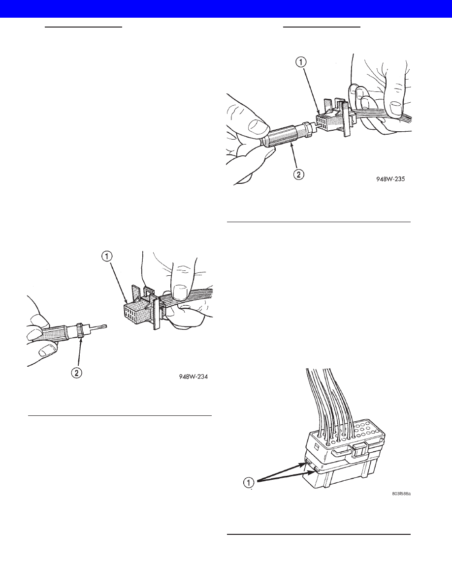
(3) Insert special tool 6742 into the terminal end of

the connector (Fig. 10).

(4) Using special tool 6742, release the locking fin-

gers on the terminal (Fig. 11).

(5) Pull on the wire to remove it from the connec-

tor.

(6) Repair or replace the terminal as necessary.

INSTALLATION

(1) Reset the terminal locking tang.
(2) Insert the removed wire in the same cavity on

the repair connector.

(3) Repeat steps for each wire in the connector,

being sure that all wires are inserted into the proper
cavities. For additional connector pin-out identifica-
tion, refer to the wiring diagrams.

(4) Connect connector to its mating half/compo-

nent.

(5) Connect battery and test all affected systems.

CONNECTOR - THOMAS AND
BETTS

REMOVAL

(1) Disconnect battery.
(2) Disconnect the connector from its mating half/

component.

(3) Push in the two lock tabs on the side of the

connector (Fig. 12).

Fig. 10 MOLEX CONNECTOR REPAIR

1 - CONNECTOR
2 - SPECIAL TOOL 6742

Fig. 11 USING SPECIAL TOOL 6742

1 - CONNECTOR
2 - SPECIAL TOOL 6742

Fig. 12 THOMAS AND BETTS CONNECTOR LOCK

RELEASE TABS

1 - LOCK TABS

WJ

8Wa-01 WIRING DIAGRAM INFORMATION

8Wa - 01 - 9

CONNECTOR - AUGAT (Continued)

2001 JEEP GRAND CHEROKEE

(4) Insert the probe end of special tool 6934 into

the back of the connector cavity (Fig. 13).

(5) Grasp the wire and tool 6934, then slowly

remove the wire and terminal from the connector.

(6) Repair or replace the terminal as necessary.

INSTALLATION

(1) Reset the terminal locking tang.
(2) Insert the removed wire in the same cavity on

the repair connector.

(3) Repeat steps for each wire in the connector,

being sure that all wires are fully seated into the
proper cavities. For additional connector pin-out
identification, refer to the wiring diagrams.

(4) Push in the single lock tab on the side of the

connector (Fig. 14).

(5) Connect connector to its mating half/compo-

nent.

(6) Connect battery and test all affected systems.

DIODE

REMOVAL

(1) Disconnect the battery.
(2) Locate the diode in the harness, and remove

the protective covering.

(3) Remove the diode from the harness, pay atten-

tion to the current flow direction (Fig. 15).

INSTALLATION

(1) Remove the insulation from the wires in the

harness. Only remove enough insulation to solder in
the new diode.

(2) Install the new diode in the harness, making

sure current flow is correct. If necessary, refer to the
appropriate wiring diagram for current flow (Fig. 15).

(3) Solder the connection together using rosin core

type solder only. Do not use acid core solder.

(4) Tape the diode to the harness using electrical

tape. Make sure the diode is completely sealed from
the elements.

(5) Re-connect the battery and test affected sys-

tems.

Fig. 13 REMOVING WIRE TERMINAL

1 - SPECIAL TOOL 6934

Fig. 14 SINGLE LOCK TAB

1 - SINGLE LOCK TAB

Fig. 15 DIODE IDENTIFICATION

1 - CURRENT FLOW
2 - BAND AROUND DIODE INDICATES CURRENT FLOW
3 - DIODE AS SHOWN IN THE DIAGRAMS

8Wa - 01 - 10

8Wa-01 WIRING DIAGRAM INFORMATION

WJ

CONNECTOR - THOMAS AND BETTS (Continued)

2001 JEEP GRAND CHEROKEE

TERMINAL

REMOVAL

(1) Disconnect battery.
(2) Disconnect the connector being repaired from

its mating half/component.

(3) Remove

the

connector

locking

wedge,

if

required (Fig. 16).

(4) Position the connector locking finger away from

the terminal using the proper pick from special tool
kit 6680. Pull on the wire to remove the terminal
from the connector (Fig. 17) (Fig. 18).

(5) Cut the wire 6 inches from the back of the con-

nector.

INSTALLATION

(1) Select a wire from the terminal repair assem-

bly that best matches the color wire being repaired.

(2) Cut the repair wire to the proper length and

remove one–half (1/2) inch of insulation.

(3) Splice the repair wire to the wire harness .
(4) Insert the repaired wire into the connector.
(5) Install the connector locking wedge, if required,

and reconnect the connector to its mating half/compo-
nent.

(6) Re-tape the wire harness starting at 1–1/2

inches behind the connector and 2 inches past the
repair.

(7) Connect battery and test all affected systems.

Fig. 16 CONNECTOR LOCKING WEDGE TAB

(TYPICAL)

1 - CONNECTOR
2 - CONNECTOR LOCKING WEDGE TAB

Fig. 17 TERMINAL REMOVAL

1 - CONNECTOR
2 - FROM SPECIAL TOOL KIT 6680

Fig. 18 TERMINAL REMOVAL USING SPECIAL TOOL

1 - FROM SPECIAL TOOL KIT 6680
2 - CONNECTOR

WJ

8Wa-01 WIRING DIAGRAM INFORMATION

8Wa - 01 - 11

2001 JEEP GRAND CHEROKEE

WIRE

STANDARD PROCEDURE - WIRE SPLICING

When splicing a wire, it is important that the cor-

rect gage be used as shown in the wiring diagrams.

(1) Remove one-half (1/2) inch of insulation from

each wire that needs to be spliced.

(2) Place a piece of adhesive lined heat shrink tub-

ing on one side of the wire. Make sure the tubing will
be long enough to cover and seal the entire repair
area.

(3) Place the strands of wire overlapping each

other inside of the splice clip (Fig. 19).

(4) Using crimping tool, Miller p/n 8272, crimp the

splice clip and wires together (Fig. 20)

(5) Solder the connection together using rosin core

type solder only (Fig. 21).

CAUTION: DO NOT USE ACID CORE SOLDER.

(6) Center the heat shrink tubing over the joint

and heat using a heat gun. Heat the joint until the
tubing is tightly sealed and sealant comes out of both
ends of the tubing (Fig. 22).

Fig. 19 SPLICE CLIP

Fig. 20 CRIMPING TOOL

Fig. 21 SOLDER

Fig. 22 HEAT SHRINK TUBING

8Wa - 01 - 12

8Wa-01 WIRING DIAGRAM INFORMATION

WJ

2001 JEEP GRAND CHEROKEE


Content   ..  733  734  735  736   ..