Jeep Grand Cherokee WJ. Manual - part 719


  Index      Jeep     Jeep Grand Cherokee WJ - service repair manual 2001 year


Search            


Content   ..  717  718  719  720   ..


Jeep Grand Cherokee WJ. Manual - part 719


ENGINE 4.7L

TABLE OF CONTENTS

page

page

RADIATOR FAN

DESCRIPTION

. . . . . . . . . . . . . . . . . . . . . . . . . 21

OPERATION

. . . . . . . . . . . . . . . . . . . . . . . . . . . 22

REMOVAL

. . . . . . . . . . . . . . . . . . . . . . . . . . . . . 23

CLEANING

. . . . . . . . . . . . . . . . . . . . . . . . . . . . 24

INSTALLATION

. . . . . . . . . . . . . . . . . . . . . . . . . 24

RADIATOR

DESCRIPTION

. . . . . . . . . . . . . . . . . . . . . . . . . 25

REMOVAL

. . . . . . . . . . . . . . . . . . . . . . . . . . . . . 25

CLEANING

. . . . . . . . . . . . . . . . . . . . . . . . . . . . 26

INSPECTION . . . . . . . . . . . . . . . . . . . . . . . . . . . 27
INSTALLATION

. . . . . . . . . . . . . . . . . . . . . . . . . 27

WATER PUMP - 4.7L

DESCRIPTION

. . . . . . . . . . . . . . . . . . . . . . . . . 27

OPERATION

. . . . . . . . . . . . . . . . . . . . . . . . . . . 28

DIAGNOSIS AND TESTING

. . . . . . . . . . . . . . . . 28

WATER PUMP

. . . . . . . . . . . . . . . . . . . . . . . . 28

REMOVAL

. . . . . . . . . . . . . . . . . . . . . . . . . . . . . 29

CLEANING

. . . . . . . . . . . . . . . . . . . . . . . . . . . . 29

INSPECTION . . . . . . . . . . . . . . . . . . . . . . . . . . . 29
INSTALLATION

. . . . . . . . . . . . . . . . . . . . . . . . . 29

ENGINE COOLANT TEMP SENSOR

REMOVAL

. . . . . . . . . . . . . . . . . . . . . . . . . . . . . 30

INSTALLATION

. . . . . . . . . . . . . . . . . . . . . . . . . 30

RADIATOR FAN

DESCRIPTION

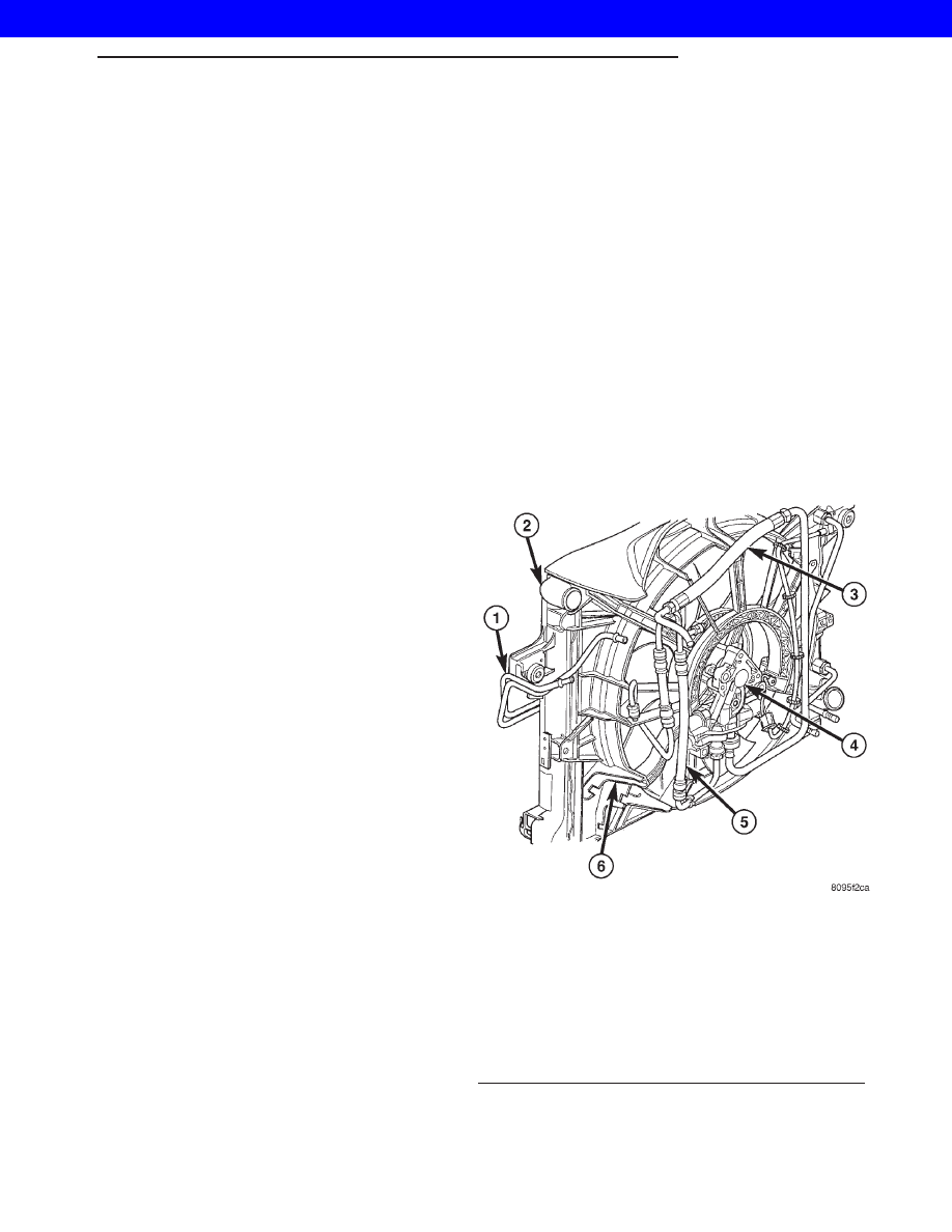
The hydraulic fan (Fig. 1) used on vehicles

equipped the 4.7L engine, replaces both the electric
fan and the engine driven mechanical fan. The
hydraulic cooling fan is integral to the fan shroud
and is located between the radiator and the engine.

The power steering pump supplies the hydraulic

fluid and pressure to rotate the cooling fan blade,
while the electrical part of the fan is controlled by
the JTEC.

The hydraulic fan drive (motor) consists of the

three major following components:

• Steering flow control valve

• Fan control valve

• Two stage G-rotor hydraulic drive
The hydraulic fan and drive is not serviceable.

Therefore any failure of the fan blade, hydraulic fan
drive or fan shroud requires replacement of the fan
module because the fan blade and hydraulic fan drive
are matched and balanced as a system and servicing
either separately would disrupt this balance.

For hydraulic fluid routing information refer to

(Fig. 2).

CAUTION: Do not attempt to service the hydraulic
cooling fan or fan drive separately replace the cool-
ing module as an assembly. Failure to do so may
cause severe damage to the hydraulic cooling fan
assembly.

Fig. 1 HYDRAULIC RADIATOR COOLING FAN AND

FAN DRIVE

1 - POWER STEERING FLUID COOLER
2 - RADIATOR
3 - HIGH PRESSURE LINE FROM STEERING GEAR PUMP TO
HYDRAULIC FAN MOTOR
4 - HYDRAULIC FAN MOTOR
5 - HIGH PRESSURE LINE FROM HYDRAULIC FAN MOTOR TO
STEERING GEAR
6 - FAN SHROUD

WG

ENGINE 4.7L

7s - 21

2001 JEEP GRAND CHEROKEE

OPERATION

The hydraulic radiator cooling fan used on the

Grand Cherokee with the 4.7L engine replaces both
the electric fan and the engine driven mechanical
fan. The use of this hydraulic fan provides the 4.7L
equipped Grand Cherokee with heavy trailer tow
capability while at the same time reducing unneces-
sary power drain on both the engine and the vehicles
electrical system.

HYDRAULIC FAN STRATEGY

The hydraulic radiator cooling fan is controlled by

the JTEC. A PWM (Pulse With Modulated) signal
from the JTEC controls the fan from 0 to 100% of the
available fan speed. There are four inputs to the
JTEC that determine what speed percentage of fan is
required by the vehicle. These inputs are:

• Engine Coolant Temperature

• Transmission Oil Temperature

• Battery Temperature

• A/C System Pressure

By monitoring these four parameters, the JTEC

can determine if cooling airflow is required. If airflow
is required, the JTEC will slowly ramp up (speed up)
the fan speed until the parameter(s) are under con-
trol. Once the temperature or pressure is reduced to
within operating parameters the fan will ramp up,
ramp down, or hold its speed to maintain the temper-
ature / pressure requirements.

NOTE: Even if the JTEC is not requesting fan on
operation the fan blade will spin between 100 and
500 RPM when the vehicle is at idle. This is due to
a controlled minimum oil flow requirement through
the fan drive motor.

RADIATOR COOLING FAN HYDRAULIC FLUID PATH

Hydraulic fluid is pumped through the power

steering pump, from the pump the fluid travels
though a high pressure delivery line to the fan drive
motor. As fluid is diverted through the G-rotors, rota-
tional motion is created as fluid moves from the high-

Fig. 2 HYDRAULIC FAN FLUID FLOW CIRCUIT

1 - POWER STEERING RESERVOIR
2 - POWER STEERING PUMP
3 - HYDRAULIC FAN DRIVE ASSEMBLY
4 - FAN BLADE

5 - HYDRAULIC FAN CONTROL SOLENOID
6 - POWER STEERING OIL COOLER
7 - STEERING GEAR

7s - 22

ENGINE 4.7L

WG

RADIATOR FAN (Continued)

2001 JEEP GRAND CHEROKEE

pressure (inlet) side of the motor to the low-pressure
(outlet) side. Fluid exiting the drive motor is divided
into two paths. Path one continues through a high
pressure delivery line to the vehicles steering gear to
provide steering assist. and path two sends fluid
back to the power steering pump through a low pres-
sure line. Fluid exits the steering gear under low
pressure and travels through a low pressure line to
the power steering fluid cooler to be cooled before
being returned back the the power steering fluid res-
ervoir (Fig. 2).

NOTE: There is a steering flow control valve located
in the fan drive motor. This valve operates like the
flow control valve found in the typical power steer-
ing pump. Because of the design of the valve steer-
ing assist can not be effected by the radiator
cooling fan even during fan drive failure.

REMOVAL

(1) Raise vehicle on hoist.
(2) Drain cooling system. (Refer to 7 - COOLING -

STANDARD PROCEDURE)

NOTE: The hydraulic fan drive is driven by the
power steering pump. When removing lines or
hoses from fan drive assembly use a drain pan to
catch any power steering fluid that may exit the fan
drive or the lines and hoses.

NOTE: When ever the high pressure line fittings are
removed from the hydraulic fan drive the O-rings
must be replaced.

(3) Disconnect two high pressure lines at hydraulic

fan drive (Fig. 3). Remove and discard o-rings from
line fittings.

(4) Disconnect low pressure return hose at hydrau-

lic fan drive (Fig. 3).

NOTE: The lower mounting bolts can only be
accessed from under vehicle.

(5) Remove two lower mounting bolts from the

shroud (Fig. 5).

(6) Lower vehicle.
(7) Disconnect the electrical connector for the fan

control solenoid.

(8) Disconnect the radiator upper hose at the radi-

ator and position out of the way.

(9) Disconnect the power steering grar outlet hose

and fluid return hose at the cooler (Fig. 4).

(10) Remove two upper mounting bolts from the

shroud (Fig. 5).

(11) Remove the shroud and fan drive from vehi-

cle.

Fig. 3 HYDRAULIC LINES/HOSES AND ELECTRICAL

CONNECTOR

1 - LOW PRESSURE RETURN HOSE
2 - HIGH PRESSURE LINE (OUTLET)
3 - HIGH PRESSURE LINE (INLET)
4 - HYDRAULIC FAN DRIVE

Fig. 4 POWER STEERING GEAR OUTLET AND

RETURN HOSES

1 - POWER STEERING COOLER RETURN HOSE
2 - POWER STEERING COOLER SUPPLY HOSE

WG

ENGINE 4.7L

7s - 23

RADIATOR FAN (Continued)

2001 JEEP GRAND CHEROKEE

CLEANING

Clean the fan blades using a mild soap and water.

Do not use an abrasive to clean the blades.

INSTALLATION

CAUTION: There is an external ground wire con-
nected to the hydraulic fan drive located at the elec-
trical connector on the fan assembly. This ground
MUST remain connected at all times. Failure to
ensure ground wire is connected when engine is
operating can cause severe damage to the JTEC
module.

(1) Position fan drive and shroud in vehicle.
(2) Install fan shroud upper mounting bolts. Do

not tighten at this time.

(3) Install radiator upper hose onto radiator.
(4) Connect power steering cooler hoses.
(5) Raise vehicle on hoist.
(6) Install

fan

shroud

lower

mounting

bolts.

Tighten to 6 N·m (50 in. lbs.).

NOTE: When ever the high pressure line fittings are
removed from the hydraulic fan drive the o-rings
located on the fittings must be replaced.

(7) Lubricate the o-rings on the fittings with power

steering fluid then connect inlet and outlet high pres-
sure lines to fan drive (Fig. 6). Tighten inlet line to

49 N·m (36 ft. lbs.) tighten outlet line to 29 N·m (21.5
ft. lbs.).

(8) Connect low pressure return hose to fan drive

(Fig. 6).

(9) Lower vehicle.
(10) Install radiator upper hose.
(11) Connect electrical connector for hydraulic fan

control solenoid.

(12) Tighten fan shroud upper mounting bolts to 6

N·m (50 in. lbs.).

(13) Refill cooling system (Refer to 7 - COOLING -

STANDARD PROCEDURE).

CAUTION: Do not run engine with power steering
fluid below the full mark in the reservoir. Sever
damage to the hydraulic cooling fan or the engine
can occur.

(14) Refill power steering fluid reservoir and bleed

air from steering system (Refer to 19 - STEERING/
PUMP - STANDARD PROCEDURE).

(15) Run engine and check for leaks.

Fig. 5 FAN SHROUD MOUNTING BOLT LOCATIONS

1 - FAN SHROUD UPPER MOUNTING BOLT LOCATIONS
2 - FAN SHROUD LOWER MOUNTING BOLT LOCATIONS

Fig. 6 HYDRAULIC LINES/HOSES AND ELECTRICAL

CONNECTOR

1 - LOW PRESSURE RETURN HOSE
2 - HIGH PRESSURE LINE (OUTLET)
3 - HIGH PRESSURE LINE (INLET)
4 - HYDRAULIC FAN DRIVE

7s - 24

ENGINE 4.7L

WG

RADIATOR FAN (Continued)

2001 JEEP GRAND CHEROKEE


Content   ..  717  718  719  720   ..