Jeep Grand Cherokee WJ. Manual - part 716


  Index      Jeep     Jeep Grand Cherokee WJ - service repair manual 2001 year


Search            


Content   ..  714  715  716  717   ..


Jeep Grand Cherokee WJ. Manual - part 716


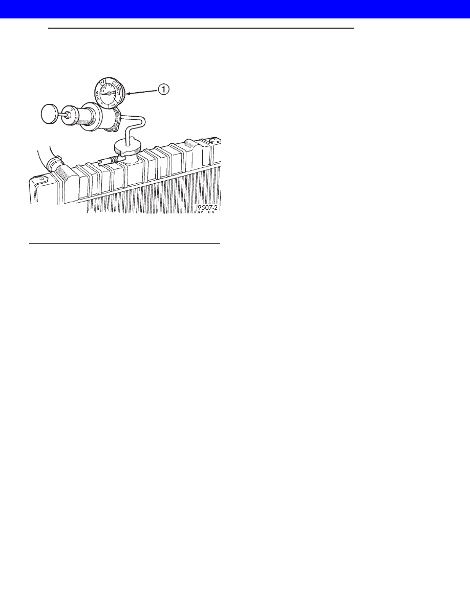
Attach pressure tester (7700 or an equivalent) to

radiator filler neck (Fig. 2).

Operate tester pump to apply 103.4 kPa (15 psi)

pressure to system. If hoses enlarge excessively or
bulges while testing, replace as necessary. Observe
gauge pointer and determine condition of cooling sys-
tem according to following criteria:

Holds Steady: If pointer remains steady for two

minutes, serious coolant leaks are not present in sys-
tem. However, there could be an internal leak that
does not appear with normal system test pressure. If
it is certain that coolant is being lost and leaks can-
not be detected, inspect for interior leakage or per-
form Internal Leakage Test.

Drops Slowly: Indicates a small leak or seepage

is occurring. Examine all connections for seepage or
slight leakage with a flashlight. Inspect radiator,
hoses, gasket edges and heater. Seal small leak holes
with a Sealer Lubricant (or equivalent). Repair leak
holes

and

inspect

system

again

with

pressure

applied.

Drops Quickly: Indicates that serious leakage is

occurring. Examine system for external leakage. If
leaks are not visible, inspect for internal leakage.
Large radiator leak holes should be repaired by a
reputable radiator repair shop.

INTERNAL LEAKAGE INSPECTION

Remove engine oil pan drain plug and drain a

small amount of engine oil. If coolant is present in
the pan, it will drain first because it is heavier than
oil. An alternative method is to operate engine for a
short period to churn the oil. After this is done,
remove engine dipstick and inspect for water glob-
ules. Also inspect transmission dipstick for water
globules and transmission fluid cooler for leakage.

WARNING: WITH RADIATOR PRESSURE TESTER
TOOL INSTALLED ON RADIATOR, DO NOT ALLOW
PRESSURE TO EXCEED 110 KPA (20 PSI). PRES-
SURE WILL BUILD UP QUICKLY IF A COMBUSTION
LEAK

IS

PRESENT.

TO

RELEASE

PRESSURE,

ROCK

TESTER

FROM

SIDE

TO

SIDE.

WHEN

REMOVING TESTER, DO NOT TURN TESTER MORE
THAN 1/2 TURN IF SYSTEM IS UNDER PRESSURE.

Operate engine without pressure cap on radiator

until thermostat opens. Attach a Pressure Tester to
filler neck. If pressure builds up quickly it indicates a
combustion leak exists. This is usually the result of a
cylinder head gasket leak or crack in engine. Repair
as necessary.

If there is not an immediate pressure increase,

pump the Pressure Tester. Do this until indicated
pressure is within system range of 110 kPa (16 psi).
Fluctuation of gauge pointer indicates compression or
combustion leakage into cooling system.

Because the vehicle is equipped with a catalytic

converter, do not remove spark plug cables or short
out cylinders to isolate compression leak.

If the needle on dial of pressure tester does not

fluctuate, race engine a few times to check for an
abnormal amount of coolant or steam. This would be
emitting from exhaust pipe. Coolant or steam from
exhaust pipe may indicate a faulty cylinder head gas-
ket, cracked engine cylinder block or cylinder head.

A convenient check for exhaust gas leakage into

cooling system is provided by a commercially avail-
able Block Leak Check tool. Follow manufacturers
instructions when using this product.

COMBUSTION LEAKAGE TEST - WITHOUT
PRESSURE TESTER

DO NOT WASTE reusable coolant. If solution is

clean, drain coolant into a clean container for reuse.

WARNING: DO NOT REMOVE CYLINDER BLOCK
DRAIN PLUGS OR LOOSEN RADIATOR DRAIN-
COCK WITH SYSTEM HOT AND UNDER PRESSURE.
SERIOUS BURNS FROM COOLANT CAN OCCUR.

Drain

sufficient

coolant

to

allow

thermostat

removal. (Refer to 7 - COOLING/ENGINE/ENGINE
COOLANT THERMOSTAT - REMOVAL). Remove
accessory drive belt (Refer to 7 - COOLING/ACCES-
SORY DRIVE/DRIVE BELTS - REMOVAL).

Add coolant to radiator to bring level to within 6.3

mm (1/4 in) of top of thermostat housing.

CAUTION:

Avoid

overheating.

Do

not

operate

engine for an excessive period of time. Open drain-
cock immediately after test to eliminate boil over.

Fig. 2 Pressure Testing Cooling System—Typical

1 - TYPICAL COOLING SYSTEM PRESSURE TESTER

WG

COOLING

7s - 9

COOLING (Continued)

2001 JEEP GRAND CHEROKEE

Start engine and accelerate rapidly three times, to

approximately 3000 rpm while observing coolant. If
internal engine combustion gases are leaking into
cooling system, bubbles will appear in coolant. If bub-
bles do not appear, internal combustion gas leakage
is not present.

STANDARD PROCEDURE - FLUSHING
COOLERS AND TUBES

When a transmission failure has contaminated the

fluid, the oil cooler(s) must be flushed. The torque
converter must also be replaced. This will insure that
metal particles or sludged oil are not later trans-
ferred back into the reconditioned (or replaced) trans-
mission.

The only recommended procedure for flushing cool-

ers and lines is to use Tool 6906-B Cooler Flusher.

WARNING:
WEAR PROTECTIVE EYEWEAR THAT MEETS THE
REQUIREMENTS OF OSHA AND ANSI Z87.1–1968.
WEAR STANDARD INDUSTRIAL RUBBER GLOVES.
KEEP LIGHTED CIGARETTES, SPARKS, FLAMES,
AND OTHER IGNITION SOURCES AWAY FROM THE
AREA TO PREVENT THE IGNITION OF COMBUSTI-
BLE LIQUIDS AND GASES. KEEP A CLASS (B) FIRE
EXTINGUISHER

IN

THE

AREA

WHERE

THE

FLUSHER WILL BE USED.
KEEP THE AREA WELL VENTILATED.
DO NOT LET FLUSHING SOLVENT COME IN CON-
TACT WITH YOUR EYES OR SKIN: IF EYE CONTAM-
INATION OCCURS, FLUSH EYES WITH WATER FOR
15 TO 20 SECONDS. REMOVE CONTAMINATED
CLOTHING AND WASH AFFECTED SKIN WITH
SOAP AND WATER. SEEK MEDICAL ATTENTION.

(1) Remove cover plate filler plug on Tool 6906-B.

Fill reservoir 1/2 to 3/4 full of fresh flushing solution.
Flushing solvents are petroleum based solutions gen-
erally used to clean automatic transmission compo-
nents. DO NOT use solvents containing acids, water,
gasoline, or any other corrosive liquids.

(2) Reinstall filler plug on Tool 6906-B.
(3) Verify pump power switch is turned OFF. Con-

nect red alligator clip to positive (+) battery post.
Connect black (-) alligator clip to a good ground.

(4) Disconnect the cooler lines at the transmission.

NOTE: When flushing transmission cooler and
lines, ALWAYS reverse flush.

NOTE: The converter drainback valve must be
removed and an appropriate replacement hose
installed to bridge the space between the transmis-
sion cooler line and the cooler fitting. Failure to
remove the drainback valve will prevent reverse
flushing the system. A suitable replacement hose
can be found in the adapter kit supplied with the
flushing tool.

(5) Connect the BLUE pressure line to the OUT-

LET (From) cooler line.

(6) Connect the CLEAR return line to the INLET

(To) cooler line

(7) Turn pump ON for two to three minutes to

flush cooler(s) and lines.

(8) Turn pump OFF.
(9) Disconnect CLEAR suction line from reservoir

at cover plate. Disconnect CLEAR return line at
cover plate, and place it in a drain pan.

(10) Turn pump ON for 30 seconds to purge flush-

ing solution from cooler and lines. Turn pump OFF.

(11) Place CLEAR suction line into a one quart

container of Mopar

t ATF +4, type 9602, Automatic

Transmission Fluid.

(12) Turn pump ON until all transmission fluid is

removed from the one quart container and lines. This
purges any residual cleaning solvent from the trans-
mission cooler and lines. Turn pump OFF.

(13) Disconnect alligator clips from battery. Recon-

nect flusher lines to cover plate, and remove flushing
adapters from cooler lines.

7s - 10

COOLING

WG

COOLING (Continued)

2001 JEEP GRAND CHEROKEE

SPECIFICATIONS

TORQUE

DESCRIPTION

N·m

Ft.

In.

Lbs.

Lbs.

Automatic Belt Tensioner to
Mounting

Bracket—Bolt

4.0L

28

250

4.7L

41

30

Automatic Belt Tensioner
Pulley—

Bolt

(4.7L)

61

45

Block Heater—Bolt

4.0L

4

32

4.7L

2

17

Fan Blade Assy. to Viscous
Drive—

Bolts 4.0L

23

200

Generator Mounting—Bolts
4.0L

57

42

Radiator Upper Isolator to

Crossmember—Nuts

3

20

Radiator Upper Isolator to
Radiator—

Nuts

4

36

DESCRIPTION

N·m

Ft.

In.

Lbs.

Lbs.

Radiator Brace—Bolts

10

90

Thermostat Housing—Bolts

4.0L

22

16

4.7L

13

115

Upper Radiator Crossmember
to

Body—Bolts

10

90

Water Pump—Bolts

4.0L

23

17

4.7L

54

40

Water Pump Pulley to Water
Pump—

Bolts 4.0L

28

250

High Pressure Inlet Hose to
Hydraulic Fan Drive—1/2 inch
Fitting

49

36

High Pressure Outlet Hose to
Steering Gear—3/8 inch
Fitting

29

21.5

Fan Shroud to Radiator
Mounting Bolts

6

50

WG

COOLING

7s - 11

COOLING (Continued)

2001 JEEP GRAND CHEROKEE

ENGINE 3.1L DIESEL

TABLE OF CONTENTS

page

page

ENGINE 3.1L DIESEL

DESCRIPTION . . . . . . . . . . . . . . . . . . . . . . . . . . . 12
OPERATION. . . . . . . . . . . . . . . . . . . . . . . . . . . . . 12
DIAGNOSIS AND TESTING . . . . . . . . . . . . . . . . . 13

RADIATOR FLOW TEST . . . . . . . . . . . . . . . . . . 13

SPECIFICATIONS . . . . . . . . . . . . . . . . . . . . . . . . 13

COOLANT LEVEL SENSOR

DESCRIPTION . . . . . . . . . . . . . . . . . . . . . . . . . . . 14
OPERATION. . . . . . . . . . . . . . . . . . . . . . . . . . . . . 14
REMOVAL . . . . . . . . . . . . . . . . . . . . . . . . . . . . . . 14
INSTALLATION. . . . . . . . . . . . . . . . . . . . . . . . . . . 14

ENGINE 3.1L DIESEL

DESCRIPTION

This Service Manual Supplement includes

ONLY the information that is new or updated
for 2001 Model Year. All other Service Manual
information is in the 2000 Model Year Service
Manual.

When you are using this information you may

be referred to another section of the Service
Manual. The “Refer To” is written differently
than in prior years.

DESCRIPTION

The pressure/vent cap is threaded-on to the coolant

tank. This cap releases excess pressure at some point
within a range of 90-117 kPa (13- 17 psi). The actual
pressure relief point (in pounds) is labeled on top of
the cap (Fig. 1).

OPERATION

The cooling system will operate at pressures up to

103 kPa (15 psi). This results in a higher coolant
boiling point allowing increased radiator cooling
capacity. The cap (Fig. 1) contains a spring-loaded
pressure relief valve. This valve opens when system
pressure reaches approximately 103 kPa (15 psi).

When the engine is cooling down, vacuum is

formed within the cooling system. To prevent collapse
of the radiator and coolant hoses from this vacuum, a
vacuum valve is used within the cap. This valve pre-
vents excessive pressure differences from occurring
between the closed cooling system and the atmo-
sphere. If the vacuum valve is stuck shut, the radia-
tor and/or cooling system hoses will collapse on cool-
down.

NOTE: Do not use any type of tool when tightening
the cap. Hand tighten only.

Fig. 1 COOLANT TANK PRESSURE/VENT CAP

1 - RELEASE PRESSURE
2 - CAP COVER
3 - SPRING
4 - GASKET
5 - RUBBER VACUUM VALVE
6 - PRESSURE VALVE

7s - 12

ENGINE 3.1L DIESEL

WG

2001 JEEP GRAND CHEROKEE


Content   ..  714  715  716  717   ..