Jeep Grand Cherokee WJ. Manual - part 706


  Index      Jeep     Jeep Grand Cherokee WJ - service repair manual 2001 year


Search            


Content   ..  704  705  706  707   ..


Jeep Grand Cherokee WJ. Manual - part 706


(18) Seat ring gear side dummy bearing (Fig. 11).
(19) Position the dial indicator plunger on a flat

surface between the ring gear bolt heads. (Fig. 12).

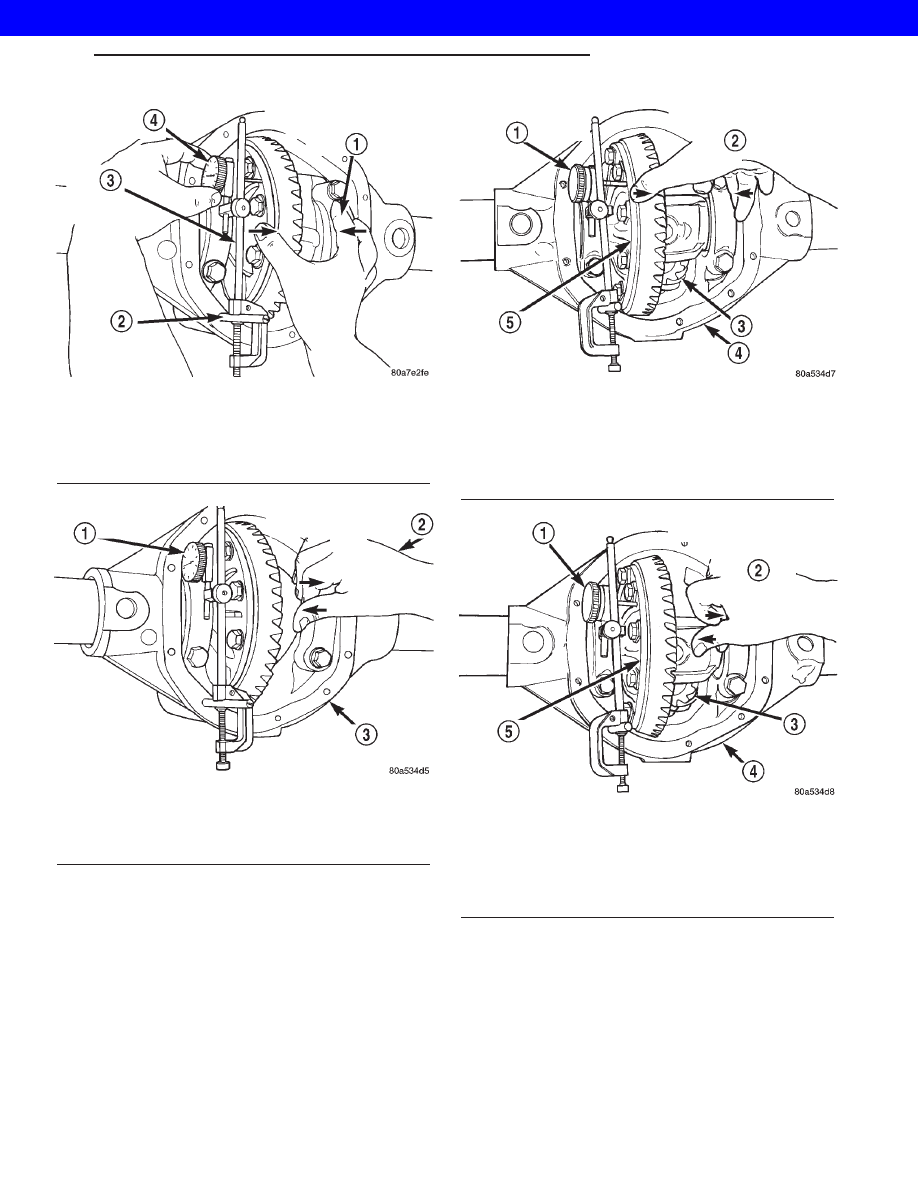
(20) Push and hold differential case toward pinion

gear and zero dial indicator (Fig. 15).

(21) Push and hold differential case to ring gear

side of the housing and record dial indicator reading
(Fig. 16). Add dummy shim thickness to this reading.
This will be the total shim thickness to achieve zero
backlash.

(22) Subtract 0.076 mm (0.003 in.) from the dial

indicator reading to compensate for backlash between
ring and pinion gears. This total is the thickness
shim required to achieve proper backlash.

(23) Subtract the backlash shim thickness from

the total preload shim thickness. The remainder is
the shim thickness required on the pinion side of the
housing.

(24) Rotate dial indicator out of the way on pilot

stud.

Fig. 13 Zero Dial Indicator

1 - FORCE DIFFERENTIAL CASE TO PINION GEAR SIDE
2 - SPECIAL TOOL - C-3288-B
3 - SPECIAL TOOL - C-3339
4 - ZERO DIAL INDICATOR FACE

Fig. 14 Differential Case and Dial Indicator

1 - READ DIAL INDICATOR
2 - FORCE DIFFERENTIAL CASE TO RING GEAR SIDE
3 - AXLE HOUSING

Fig. 15 Zero Dial Indicator

1 - ZERO DIAL INDICATOR FACE
2 - FORCE DIFFERENTIAL CASE TO PINION GEAR SIDE
3 - PINION GEAR
4 - AXLE HOUSING
5 - DIFFERENTIAL CASE

Fig. 16 Differential To Ring Gear Side

1 - READ DIAL INDICATOR
2 - FORCE DIFFERENTIAL CASE TO RING GEAR SIDE
3 - PINION GEAR
4 - AXLE HOUSING
5 - DIFFERENTIAL CASE

WG

REAR AXLE - 198RBI

3s - 25

REAR AXLE - 198RBI (Continued)

2001 JEEP GRAND CHEROKEE

(25) Remove differential case and dummy bearings

from the housing.

(26) Install side bearings and cups on differential

case.

(27) Install spreader W-129-B utilizing some items

from Adapter Set 6987, on the housing and spread
axle opening enough to receive differential case.

CAUTION: Do not spread over 0.38 mm (0.015 in.). If
housing is over-spread, it could be distorted or
damaged.

(28) Place the bearing preload shims in the hous-

ing, against the axle tubes.

(29) Install differential case into the housing.
(30) Remove spreader from the housing.
(31) Rotate the differential case several times to

seat the side bearings.

(32) Position the indicator plunger against a ring

gear tooth (Fig. 17).

(33) Push and hold ring gear upward while not

allowing the pinion gear to rotate.

(34) Zero dial indicator face to pointer.
(35) Push and hold ring gear downward while not

allowing the pinion gear to rotate. Dial indicator
reading should be between 0.12-0.20 mm (0.005-0.008
in.). If backlash is not within specifications transfer
the necessary amount of shim thickness from one
side of the axle housing to the other (Fig. 18).

(36) Verify differential case and ring gear runout

by measuring ring to pinion gear backlash at eight
locations around the ring gear. Readings should not
vary more than 0.05 mm (0.002 in.). If readings vary
more than specified, the ring gear or the differential
case is defective.

After the proper backlash is achieved, perform

Gear Contact Pattern Analysis procedure.

GEAR CONTACT PATTERN

The ring gear and pinion teeth contact patterns

will show if the pinion depth is correct in the hous-
ing. It will also show if the ring gear backlash has
been adjusted correctly. The backlash can be adjusted
within specifications to achieve desired tooth contact
patterns.

(1) Apply a thin coat of hydrated ferric oxide or

equivalent to the drive and coast side of the ring gear
teeth.

(2) Wrap, twist and hold a shop towel around the

pinion yoke to increase the turning resistance of the
pinion. This will provide a more distinct contact pat-
tern.

(3) With a boxed end wrench on a ring gear bolt,

rotate the differential case one complete revolution in
both directions while a load is being applied from
shop towel.

The areas on the ring gear teeth with the greatest

degree of contact against the pinion teeth will squee-
gee the compound to the areas with the least amount
of contact. Note and compare patterns on the ring
gear teeth to Gear Tooth Contact Patterns chart (Fig.
19) and adjust pinion depth and gear backlash as
necessary.

Fig. 17 Ring Gear Backlash Measurement

1 - DIAL INDICATOR

Fig. 18 Backlash Shim

3s - 26

REAR AXLE - 198RBI

WG

REAR AXLE - 198RBI (Continued)

2001 JEEP GRAND CHEROKEE

Fig. 19 Gear Tooth Contact Patterns

WG

REAR AXLE - 198RBI

3s - 27

REAR AXLE - 198RBI (Continued)

2001 JEEP GRAND CHEROKEE

DIFFERENTIAL BEARING PRELOAD CHECK

The final check on the differential assembly before

installing the axles is torque to rotate pinion and dif-
ferential combined. This will verify the correct differ-
ential bearing preload.

Torque to rotate the differential and pinion should

be the torque to rotate the pinion plus 0.79-1.24 N·m
(7-11 in. lbs.).

SPECIFICATIONS

REAR AXLE - 198RBI

AXLE SPECIFICATIONS

DESCRIPTION

SPECIFICATION

Axle Ratio

3.07, 3.55, 3.73, 4.10

Differential Bearing Preload

0.1 mm (0.004 in.)

Differential Side Gear Clearance

0.0-0.15 mm (0.0-0.006 in.)

Ring Gear Diameter

198 mm (7.795 in.)

Ring Gear Backlash

0.12-0.20 mm (0.005-0.008 in.)

Pinion Gear Std. Depth

96.85 mm (3.813 in.)

Pinion Bearing Preload - Original Bearings

1-2 N·m (10-20 in. lbs.)

Pinion Bearing Preload - New Bearings

1.7-3.4 N·m (15-30 in. lbs.)

TORQUE SPECIFICATIONS

DESCRIPTION

N·m

Ft. Lbs.

In. Lbs.

Differential Cover Bolts

41

30

-

Bearing Cap Bolts

77

57

-

Ring Gear Bolts

129-142

95-105

-

Pinion Nut

271-474

200-350

-

Pinion Mate Shaft Screw

16.25

12

-

Axle Bearing Retainer Plate Nuts

61

45

-

DIFFERENTIAL

REMOVAL

(1) Raise and support vehicle.
(2) Remove the lubricant fill hole plug from the

differential housing cover.

(3) Remove the differential housing cover and

allow fluid to drain.

(4) Clean the housing cavity with flushing oil, light

engine oil or lint free cloth. Do not use water,
steam, kerosene or gasoline for cleaning.

(5) Remove axle shafts.
(6) Note the reference letters stamped on the bear-

ing caps and housing machined sealing surface (Fig.
20).

(7) Loosen the differential bearing cap bolts.
(8) Position

Spreader

W-129-B,

utilizing

some

items from Adapter set 6987, with the tool dowel pins

seated in the locating holes (Fig. 21). Install the hold-
down clamps and tighten the tool turnbuckle finger-
tight.

(9) Install a Pilot Stud C-3288-B at the left side of

the differential housing. Attach Dial Indicator C-3339
to pilot stud. Load the indicator plunger against the
opposite side of the housing (Fig. 22) and zero the
indicator.

CAUTION: Do not spread over 0.38 mm (0.015 in). If
the housing is over–spread, it could be distorted or
damaged.

(10) Spread the housing enough to remove the dif-

ferential case from the housing. Measure the dis-
tance with the dial indicator (Fig. 23).

(11) Remove the dial indicator.

3s - 28

REAR AXLE - 198RBI

WG

REAR AXLE - 198RBI (Continued)

2001 JEEP GRAND CHEROKEE


Content   ..  704  705  706  707   ..