Jeep Grand Cherokee WJ. Manual - part 641
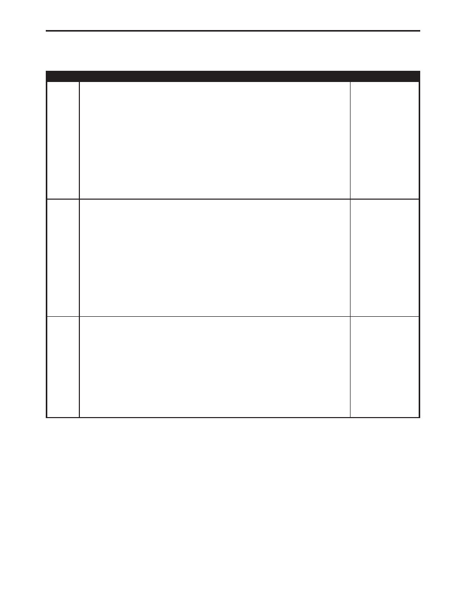
TEST
ACTION
APPLICABILITY
11
Turn the ignition off.
Remove the Transmission Control Relay from the PDC.
Disconnect the PCM harness connectors.
Disconnect the Transmission Solenoid Assembly harness connector.
Check connectors - Clean/repair as necessary
Measure the resistance between the Governor Pressure Solenoid Control circuit and
all other circuits in the Transmission Solenoid Assembly harness connector.
Is the resistance above 100 kohms between all circuits?
without 45RFE
AUTO TRANS
Yes
→
No
→
Repair the circuits that measured below 100 kohms for a short
together.
Perform TRANSMISSION VERIFICATION TEST VER - 1.
12
Turn the ignition off.
Disconnect the Transmission Solenoid Assembly harness connector.
Disconnect the PCM C2 harness connector.
NOTE: Check connectors - Clean/repair as necessary.
Measure the resistance of the Governor Pressure Solenoid Control circuit between
the Transmission Solenoid Assembly harness connector and the PCM C2 harness
connector.
Is the resistance below 5.0 ohms?
without 45RFE
AUTO TRANS
Yes
→
No
→
Repair the Governor Pressure Solenoid Control circuit for an
open.
Perform TRANSMISSION VERIFICATION TEST VER - 1.
13
Turn the ignition off.
Disconnect the PCM harness connectors.
Check connectors - Clean/repair as necessary
Measure the resistance between ground and the Governor Pressure Solenoid Control
circuit in the PCM C2 harness connector.
Is the resistance above 100 kohms?
without 45RFE
AUTO TRANS
Yes
→
No
→
Replace the Transmission Solenoid Assembly in accordance with
the Service Information.
Perform TRANSMISSION VERIFICATION TEST VER - 1.
120
DRIVEABILITY - DIESEL
P0748-GOVERNOR PRESSURE SOL CONTROL/TRANS RELAY CIR-
CUITS —
Continued