Jeep Grand Cherokee WJ. Manual - part 590


  Index      Jeep     Jeep Grand Cherokee WJ - service repair manual 2001 year


Search            


Content   ..  588  589  590  591   ..


Jeep Grand Cherokee WJ. Manual - part 590


(3) Remove two bracket mounting nuts (Fig. 17)

and remove solenoid/solenoid bracket.

INSTALLATION

(1) Position solenoid/solenoid bracket to vehicle.
(2) Install and tighten 2 bracket mounting nuts to

9 N·m (80 in. lbs.) torque.

(3) Connect vacuum lines to solenoid. Be sure vac-

uum lines are firmly connected and not leaking or
damaged. If leaking, a Diagnostic Trouble Code
(DTC) may be set with certain emission packages.

(4) Connect electrical connector to solenoid.

ROLLOVER VALVE(S)

The rollover valves(s) are/is molded into the fuel

tank and are not serviced separately. If replacement
is necessary, the fuel tank must be replaced. Refer to
Fuel Tank Removal/Installation.

LEAK DETECTION PUMP (LDP)

The LDP is located in the left/front corner of

engine compartment below air cleaner housing (Fig.
18). It is mounted to left/front inner fender sheet
metal. The LDP and LDP filter are replaced (ser-
viced) as one unit.

REMOVAL

(1) Remove air cleaner housing. Refer to Air

Cleaner Housing/Resonator/Ducts Removal/Installa-
tion.

(2) Disconnect electrical connector at LDP.
(3) Carefully remove vapor/vacuum lines at LDP.
(4) Remove 3 LDP mounting bolts (Fig. 18).
(5) Remove LDP from inner fender.

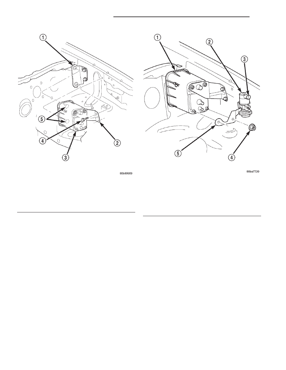
Fig. 16 EVAP Canister Removal/Installation

1 – REAR BRACKET
2 – FRONT BRACKET
3 – EVAP CANISTER
4 – CANISTER MOUNTING BOLTS
5 – ALIGNMENT PINS

Fig. 17 EVAP Canister Purge Solenoid Removal/

Installation

1 – EVAP CANISTER
2 – EVAP CANISTER PURGE SOLENOID
3 – ELECTRIC CONNECTOR
4 – MOUNTING BRACKET NUTS (2)
5 – SOLENOID BRACKET

25 - 32

EMISSION CONTROL SYSTEMS

WJ

REMOVAL AND INSTALLATION (Continued)

INSTALLATION

(1) Install LDP assembly to inner fender. Install 3

bolts and tighten to 2 N·m (20 in. lbs.) torque.

(2) Carefully install vapor/vacuum lines to LDP

and LDP filter. The vapor/vacuum lines and
hoses must be firmly connected. Check the
vapor/vacuum lines at the LDP, LDP filter and
EVAP canister purge solenoid for damage or
leaks. If a leak is present, a Diagnostic Trouble
Code (DTC) may be set.

(3) Connect electrical connector to LDP.
(4) Install

air

cleaner

housing.

Refer

to Air

Cleaner Housing/Resonator/Ducts Removal/Installa-
tion.

SPECIFICATIONS

TORQUE CHART

Description

Torque

Crankcase Breathers . . . . . . . 12 N·m (106 in. lbs.)
EVAP Canister Mounting Bolts . . . . . . . . . . 11 N·m

(100 in. lbs.)

EVAP Canister Purge Solenoid

Mounting Nuts . . . . . . . . . . . . 9 N·m (80 in. lbs.)

LDP Pump Bracket Bolts . . . . . . 2 N·m (20 in. lbs.)

Fig. 18 Leak Detection Pump (LDP) Removal/

Installation

1 – LEAK DETECTION PUMP (LDP)
2 – MOUNTING BOLTS (3)
3 – LDP FILTER
4 – LEFT/FRONT INNER FENDER
5 – ELEC. CONN.

WJ

EMISSION CONTROL SYSTEMS

25 - 33

REMOVAL AND INSTALLATION (Continued)

EMISSION CONTROL SYSTEM

TABLE OF CONTENTS

page

ON-BOARD DIAGNOSTICS—3.1L DIESEL

ENGINE . . . . . . . . . . . . . . . . . . . . . . . . . . . . . . . . 1

ON-BOARD DIAGNOSTICS—3.1L DIESEL ENGINE

TABLE OF CONTENTS

page

page

DESCRIPTION AND OPERATION

DIAGNOSTIC TROUBLE CODES . . . . . . . . . . . . . . 2

EMISSION CONTROL SYSTEM—3.1L DIESEL

ENGINE . . . . . . . . . . . . . . . . . . . . . . . . . . . . . . . 1

DESCRIPTION AND OPERATION

EMISSION CONTROL SYSTEM—3.1L DIESEL
ENGINE

DESCRIPTION

The 3.1L diesel Engine Control Module (ECM) and

Powertrain Control Module (PCM) monitor and con-
trol many different circuits in the fuel injection pump
and engine systems. If the ECM senses a problem
with a monitored circuit that indicates an actual
problem, a Diagnostic Trouble Code (DTC) will be
stored in the PCM’s memory, and eventually may
illuminate the Check Engine Lamp constantly while
the key is on. If the problem is repaired, or is inter-
mittent, the ECM will erase the DTC after 40
warm-up cycles. A warm-up cycle consists of starting
the vehicle when the engine is cold, then the engine
to warms up to a certain temperature, and finally,
the engine temperature falls to a normal operating
temperature, then the key is turned off.

Certain criteria must be met for a DTC to be

entered into ECM memory. The criteria may be a
specific range of engine rpm, engine or fuel tempera-

ture and/or input voltage to the ECM. A DTC indi-
cates that the ECM has identified an abnormal
signal in a circuit or the system. A DTC may indicate
the result of a failure, but never identify the failed
component directly.

There are several operating conditions that the

ECM does not monitor and set a DTC for. Refer to
the following Monitored Circuits and Non–Monitored
Circuits in this section.

ECM MONITORED SYSTEMS

The ECM can detect certain problems in the elec-

trical system.

Open or Shorted Circuit – The ECM will not

distiguish between an open or a short to ground,
however the ECM can determine if sensor output
(which is the input to ECM) is within proper range.
It also determines if the circuit is open or shorted.

Output Device Current Flow – The ECM senses

whether the output devices are electrically connected.

If there is a problem with the circuit, the ECM

senses whether the circuit is open, shorted to ground
(–), or shorted to (+) voltage.

WJ

EMISSION CONTROL SYSTEM

25 - 1

2000 JEEP GRAND CHEROKEE


Content   ..  588  589  590  591   ..