Jeep Grand Cherokee WJ. Manual - part 589


  Index      Jeep     Jeep Grand Cherokee WJ - service repair manual 2001 year


Search            


Content   ..  587  588  589  590   ..


Jeep Grand Cherokee WJ. Manual - part 589


VEHICLE EMISSION CONTROL INFORMATION
(VECI) LABEL

DESCRIPTION

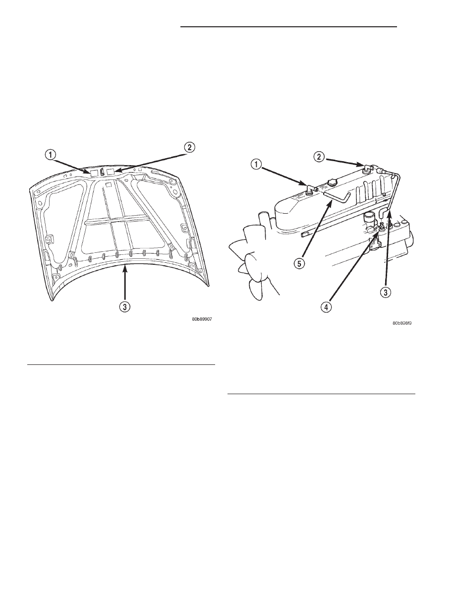
All vehicles are equipped with a combined VECI

label(s). The label is located in the engine compart-
ment on the vehicle hood (Fig. 9). Two labels are
used for vehicles built for sale in the country of Can-
ada.

OPERATION

The VECI label(s) contain the following:
• Engine family and displacement

• Evaporative family

• Emission control system schematic

• Certification application

• Spark plug and gap
The label also contains an engine vacuum sche-

matic. There are unique labels for vehicles built for
sale in the state of California and the country of
Canada. Canadian labels are written in both the
English and French languages. These labels are per-
manently attached and cannot be removed without
defacing information and destroying label.

DIAGNOSIS AND TESTING

FIXED ORIFICE FITTING/CCV SYSTEM
TEST—4.0L ENGINE

Before attempting diagnosis, be sure locations of

fixed orifice fitting and air inlet fitting (Fig. 10) have
not been inadvertently exchanged. The fixed orifice
fitting is light grey in color and is located at rear of
valve cover. The air inlet fitting is black in color and
is located at front of valve cover.

(1) Pull fixed orifice fitting (Fig. 10) from valve

cover and leave tube attached.

(2) Start engine and bring to idle speed.
(3) If fitting is not plugged, a hissing noise will be

heard as air passes through fitting orifice. Also, a
strong vacuum should be felt with a finger placed at
fitting inlet.

(4) If vacuum is not present, remove fitting orifice

fitting from tube. Start engine. If vacuum can now be
felt, replace fixed orifice fitting. Do not attempt to
clean plastic fitting.

(5) If vacuum is still not felt at hose, check line/

hose for kinks or for obstruction. If necessary, clean
out intake manifold fitting at intake manifold. Do
this by turning a 1/4 inch drill (by hand) through the
fitting to dislodge any solid particles. Blow out the

Fig. 9 VECI Label Location

1 – VECI LABEL (CANADIAN)
2 – VECI LABEL
3 – HOOD

Fig. 10 Fixed Orifice Fitting and CCV System—4.0L

Engine

1 – AIR INLET FITTING
2 – FIXED ORIFICE FITTING
3 – CCV BREATHER TUBE (REAR)
4 – INT. MAN. FITTING
5 – CCV BREATHER TUBE (FRONT)

25 - 28

EMISSION CONTROL SYSTEMS

WJ

DESCRIPTION AND OPERATION (Continued)

fitting with shop air. If necessary, use a smaller drill
to avoid removing any metal from the fitting.

(6) Return fixed orifice fitting to valve cover and

leave tube attached.

(7) Disconnect air inlet fitting and its attached

hose at front of valve cover (Fig. 10). Start engine
and bring to idle speed. Hold a piece of stiff paper
(such as a parts tag) loosely over the rubber grommet
(opening) of the disconnected air inlet fitting.

(8) The paper should be drawn against the rubber

grommet with noticeable force. This will be after
allowing approximately one minute for crankcase
pressure to reduce.

(9) If vacuum is not present, check breather hoses/

tubes/lines for obstructions or restrictions.

(10) After testing, reconnect all system hoses/

tubes/lines.

PCV VALVE/PCV SYSTEM TEST—4.7L V-8
ENGINE

(1) Disconnect PCV line/hose (Fig. 11) by discon-

necting rubber connecting hose at PCV valve fitting.

(2) Remove PCV valve at oil filler tube by rotating

PCV valve downward until locating tabs have been
freed at cam lock (Fig. 11). After tabs have cleared,
pull valve straight out from filler tube. To prevent
damage to PCV valve locating tabs, valve must
be pointed downward for removal. Do not force
valve from oil filler tube.

(3) After valve is removed, check condition of valve

o-ring (Fig. 11). Also, PCV valve should rattle when
shaken.

(4) Reconnect PCV valve to its connecting line/

hose.

(5) Start engine and bring to idle speed.
(6) If valve is not plugged, a hissing noise will be

heard as air passes through valve. Also, a strong vac-
uum should be felt with a finger placed at valve inlet.

(7) If vacuum is not felt at valve inlet, check line/

hose for kinks or for obstruction. If necessary, clean
out intake manifold fitting at rear of manifold. Do
this by turning a 1/4 inch drill (by hand) through the
fitting to dislodge any solid particles. Blow out the
fitting with shop air. If necessary, use a smaller drill
to avoid removing any metal from the fitting.

(8)

Do not attempt to clean the old PCV

valve.

(9) Return PCV valve back to oil filler tube by

placing valve locating tabs (Fig. 11) into cam lock.
Press PCV valve in and rotate valve upward. A slight
click will be felt when tabs have engaged cam lock.
Valve should be pointed towards rear of vehicle.

(10) Connect PCV line/hose and connecting rubber

hose to PCV valve.

(11) Disconnect rubber hose from fresh air fitting

at left side of air cleaner resonator box (Fig. 12).

Start engine and bring to idle speed. Hold a piece of
stiff paper (such as a parts tag) loosely over the
opening of the disconnected rubber hose.

(12) The paper should be drawn against the hose

opening with noticeable force. This will be after
allowing approximately one minute for crankcase
pressure to reduce.

(13) If vacuum is not present, disconnect each PCV

system hose at top of each breather (Fig. 12). Check
for obstructions or restrictions.

(14) If vacuum is still not present, remove each

PCV system breather (Fig. 12) from each cylinder
head. Check for obstructions or restrictions. If
plugged, replace breather. Tighten breather to 12
N·m (106 in. lbs.) torque. Do not attempt to clean
breather

(15) If vacuum is still not present, disconnect each

PCV system hose at each fitting and check for
obstructions or restrictions.

Fig. 11 PCV Valve/Oil Filler Tube—4.7L V-8 Engine

1 – O-RING
2 – LOCATING TABS
3 – CAM LOCK
4 – OIL FILLER TUBE
5 – PCV LINE/HOSE
6 – PCV VALVE

WJ

EMISSION CONTROL SYSTEMS

25 - 29

DIAGNOSIS AND TESTING (Continued)

VACUUM SCHEMATICS

A vacuum schematic for emission related items can

be found on the Vehicle Emission Control Informa-
tion (VECI) label. For label location, refer to Vehicle
Emission Control Information (VECI) Label.

LEAK DETECTION PUMP (LDP)

Refer to the appropriate Powertrain Diagnostic

Procedures service manual for LDP testing proce-
dures.

REMOVAL AND INSTALLATION

FIXED ORIFICE FITTING—4.0L ENGINE

When installing fixed orifice fitting, be sure loca-

tions of fixed orifice fitting and air inlet fitting (Fig.
13) have not been inadvertently exchanged. The fixed
orifice fitting is light grey in color and is located at
rear of valve cover. The air inlet fitting is black in
color and is located at front of valve cover.

REMOVAL

(1) Pull fixed orifice fitting (Fig. 13) from valve

cover grommet.

(2) Separate fitting from CCV breather tube.

INSTALLATION

(1) Connect fitting to CCV breather tube.
(2) Return fixed orifice fitting to valve cover grom-

met.

PCV VALVE—4.7L V-8 ENGINE

The PCV valve is located on the oil filler tube (Fig.

14). Two locating tabs are located on the side of the
valve (Fig. 14). These 2 tabs fit into a cam lock in the
oil filler tube. An o-ring seals the valve to the filler
tube.

REMOVAL

(1) Disconnect PCV line/hose (Fig. 14) by discon-

necting rubber hose at PCV valve fitting.

(2) Remove PCV valve at oil filler tube by rotating

PCV valve downward (counter-clockwise) until locat-
ing tabs have been freed at cam lock (Fig. 14). After
tabs have cleared, pull valve straight out from filler
tube. To prevent damage to PCV valve locating
tabs, valve must be pointed downward for
removal. Do not force valve from oil filler tube.

(3) After valve is removed, check condition of valve

o-ring (Fig. 14).

Fig. 12 PCV Breathers/Tubes/Hoses—4.7L V-8

Engine

1 – FRESH AIR FITTING
2 – CONNECTING TUBES/HOSES
3 – CRANKCASE BREATHERS (2)
4 – RUBBER HOSE
5 – AIR CLEANER RESONATOR

Fig. 13 Fixed Orifice Fitting—4.0L Engine

1 – AIR INLET FITTING
2 – FIXED ORIFICE FITTING
3 – CCV BREATHER TUBE (REAR)
4 – INT. MAN. FITTING
5 – CCV BREATHER TUBE (FRONT)

25 - 30

EMISSION CONTROL SYSTEMS

WJ

DIAGNOSIS AND TESTING (Continued)

INSTALLATION

(1) Return PCV valve back to oil filler tube by

placing valve locating tabs (Fig. 14) into cam lock.
Press PCV valve in and rotate valve upward. A slight
click will be felt when tabs have engaged cam lock.
Valve should be pointed towards rear of vehicle.

(2) Connect PCV line/hose and rubber hose to PCV

valve.

EVAPORATIVE (EVAP) CANISTER

The EVAP canister is located in the engine com-

partment near the brake power booster (Fig. 15).

REMOVAL

(1) Remove duty cycle EVAP canister purge sole-

noid and its mounting bracket at front of EVAP can-
ister (2 nuts).

(2) Disconnect vacuum lines at EVAP canister.

(3) Remove 2 canister mounting bolts at front

mounting bracket (Fig. 16).

(4) Remove canister from rear mounting bracket (2

pins are used (Fig. 16) to align canister to rear
bracket)

INSTALLATION

(1) Position canister to body. Guide pins into rear

bracket.

(2) Install canister mounting bolts. Tighten bolts

to 11 N·m (100 in. lbs.) torque.

(3) Connect vacuum lines. Be sure vacuum lines

are firmly connected and not leaking or damaged. If
leaking, a Diagnostic Trouble Code (DTC) may be set
with certain emission packages.

(4) Install duty cycle EVAP canister purge solenoid

and its mounting bracket to front of EVAP canister (2
nuts). Tighten nuts to 9 N·m (80 in. lbs.) torque.

EVAPORATIVE CANISTER PURGE SOLENOID

REMOVAL

The duty cycle evaporative (EVAP) canister purge

solenoid is located in the engine compartment in
front of the EVAP canister (Fig. 15).

(1) Disconnect electrical connector at solenoid.
(2) Disconnect vacuum lines at solenoid.

Fig. 14 PCV Valve/Oil Filler Tube Location

1 – O-RING
2 – LOCATING TABS
3 – CAM LOCK
4 – OIL FILLER TUBE
5 – PCV LINE/HOSE
6 – PCV VALVE

Fig. 15 EVAP Canister, EVAP Solenoid, LDP Test

Port Locations

1 – EVAP CANISTER
2 – LDP TEST PORT
3 – EVAP CANISTER PURGE SOLENOID

WJ

EMISSION CONTROL SYSTEMS

25 - 31

REMOVAL AND INSTALLATION (Continued)


Content   ..  587  588  589  590   ..