Jeep Grand Cherokee WJ. Manual - part 567


  Index      Jeep     Jeep Grand Cherokee WJ - service repair manual 2001 year


Search            


Content   ..  565  566  567  568   ..


Jeep Grand Cherokee WJ. Manual - part 567


lamp assembly must be removed from the vehicle to
access the vacuum reservoir for service. Refer to
Group 8L - Lamps for more information on compo-
nent removal.

OPERATION

Engine vacuum is stored in the vacuum reservoir.

The stored vacuum is used to operate the vacuum-
controlled vehicle accessories during periods of low
engine vacuum such as when the vehicle is climbing
a steep grade, or under other high engine load oper-
ating conditions.

The vacuum reservoir cannot be repaired and, if

faulty or damaged, it must be replaced.

DIAGNOSIS AND TESTING

A/C PERFORMANCE

The air conditioning system is designed to provide

the passenger compartment with low temperature
and low specific humidity air. The evaporator, located
in the heater-A/C housing on the dash panel below
the instrument panel, is cooled to temperatures near
the freezing point. As warm damp air passes through
the cooled evaporator, the air transfers its heat to the
refrigerant in the evaporator and the moisture in the
air condenses on the evaporator fins. During periods
of high heat and humidity, an air conditioning sys-
tem will be more effective in the Recirculation Mode.

With the system in the Recirculation Mode, only air
from the passenger compartment passes through the
evaporator. As the passenger compartment air dehu-
midifies, the air conditioning system performance
levels improve.

Humidity has an important bearing on the temper-

ature of the air delivered to the interior of the vehi-
cle. It is important to understand the effect that
humidity has on the performance of the air condition-
ing system. When humidity is high, the evaporator
has to perform a double duty. It must lower the air
temperature, and it must lower the temperature of
the moisture in the air that condenses on the evapo-
rator fins. Condensing the moisture in the air trans-
fers heat energy into the evaporator fins and tubing.
This reduces the amount of heat the evaporator can
absorb from the air. High humidity greatly reduces
the ability of the evaporator to lower the temperature
of the air.

However, evaporator capacity used to reduce the

amount of moisture in the air is not wasted. Wring-
ing some of the moisture out of the air entering the
vehicle adds to the comfort of the passengers.
Although, an owner may expect too much from their
air conditioning system on humid days. A perfor-
mance test is the best way to determine whether the
system is performing up to standard. This test also
provides valuable clues as to the possible cause of
trouble with the air conditioning system.

If the vehicle has the optional Automatic Zone Con-

trol (AZC) system, and has intermittent operational
problems or fault codes, be certain that the 16-way
wire harness connector on the heater-A/C housing is
properly seated (Fig. 7). To check this condition,
unplug the two wire harness connector halves, then
plug them in again.

Review the Service Warnings and Precautions in

the front of this group before performing this proce-
dure. The air temperature in the test room and in
the vehicle must be a minimum of 21° C (70° F) for
this test.

(1) Connect a tachometer and a manifold gauge

set.

(2) If the vehicle has the standard manual temper-

ature control, set the heater-A/C mode control switch
knob in the Panel position, the temperature control
knob in the full cool (Recirculation Mode) position,
the A/C button in the On position, and the blower
motor switch knob in the highest speed position. If
the vehicle has the optional AZC, set the heater-A/C
mode control switch knob in the Panel position, the
temperature control knob in the full cool position, the
A/C and Recirc buttons in the On position, and the
blower motor switch knob in the highest (manual)
speed position.

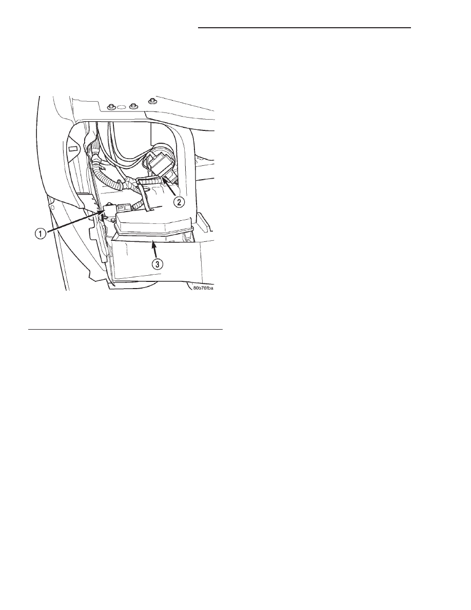
Fig. 6 Vacuum Reservoir

1 – FAN RELAY
2 – CRUISE SERVO
3 – VACUUM RESERVOIR

24 - 10

HEATING AND AIR CONDITIONING

WJ

DESCRIPTION AND OPERATION (Continued)

(3) Start the engine and hold the idle at 1,300 rpm

with the compressor clutch engaged.

(4) The engine should be at operating temperature.

The doors and windows must be open.

(5) Insert a thermometer in the driver side center

A/C (panel) outlet. Operate the engine for five min-
utes.

(6) The compressor clutch may cycle, depending

upon the ambient temperature and humidity. If the
clutch cycles, unplug the low pressure switch wire
harness connector from the switch located on the
accumulator (Fig. 8). Place a jumper wire across the
terminals of the low pressure switch wire harness
connector.

(7) With the compressor clutch engaged, record the

discharge air temperature and the compressor dis-
charge pressure.

(8) Compare the discharge air temperature to the

Performance Temperature and Pressure chart. If the
discharge air temperature is high, see Refrigerant
System Leaks and Refrigerant System Charge in this
group.

Performance Temperature and Pressure

Ambient Air
Temperature and
Humidity

21° C

(70° F @ 80%

humidity)

27° C

(80° F @ 80%

humidity)

32° C

(90° F @ 80%

humidity)

38° C

(100° F @

50% humidity)

43° C

(110° F @ 20%

humidity)

Air Temperature at
Center Panel Outlet

0 to 9° C

(32 to 48° F)

1 to 12° C

(33 to 54° F)

3 to 17° C

(37 to 63° F)

6 to 18° C

(43 to 65° F)

10 to 18° C

(50 to 65° F)

Evaporator Inlet
Pressure at Charge
Port

151 to 262 kPa

(22 to 38 psi)

221 to 248

kPa

(32 to 36 psi)

262 to 296

kPa

(38 to 43 psi)

303 kPa

(44 psi)

310 kPa

(45 psi)

Compressor Discharge
Pressure

900 to 1380

kPa

(130 to 200

psi)

1380 to 2070

kPa

(200 to 300

psi)

1720 to 2140

kPa

(250 to 310

psi)

1860 to 2140

kPa

(270 to 310

psi)

2070 to 2550

kPa

(300 to 370 psi)

Note: The discharge air temperatures will be lower if the humidity is less than the percentages shown.

Fig. 7 16-Way Wire Harness Connector (AZC)

1 – INSTRUMENT PANEL
2 – HEATER AND AIR CONDITIONER HOUSING
3 – INSTRUMENT PANEL WIRE HARNESS
4 – BLOWER MOTOR

Fig. 8 Accumulator and Low Pressure Switch

1 – SERVICE PORT
2 – LOW PRESSURE SWITCH
3 – ACCUMULATOR
4 – SUPPORT BRACKET

WJ

HEATING AND AIR CONDITIONING

24 - 11

DIAGNOSIS AND TESTING (Continued)

(9) Compare the compressor discharge pressure to

the Performance Temperature and Pressure chart. If

the compressor discharge pressure is high, see the
Pressure Diagnosis chart.

Pressure Diagnosis

Condition

Possible Causes

Correction

Rapid compressor clutch

cycling (ten or more cycles

per minute).

1. Low refrigerant system

charge.

1. See Refrigerant System Leaks in this group.

Test the refrigerant system for leaks. Repair,

evacuate and charge the refrigerant system, if

required.

Equal pressures, but the
compressor clutch does not
engage.

1. No refrigerant in the
refrigerant system.
2. Faulty fuse.
3. Faulty compressor clutch
coil.
4. Faulty compressor clutch
relay.
5. Improperly installed or
faulty low pressure switch.
6. Faulty high pressure
switch.
7. Faulty Powertrain Control
Module (PCM).

1. See Refrigerant System Leaks in this group.
Test the refrigerant system for leaks. Repair,
evacuate and charge the refrigerant system, if
required.
2. Check the fuses in the Power Distribution
Center and the fuseblock module. Repair the
shorted circuit or component and replace the
fuses, if required.
3. See Compressor Clutch Coil in this group. Test
the compressor clutch coil and replace, if
required.
4. See Compressor Clutch Relay in this group.
Test the compressor clutch relay and relay
circuits. Repair the circuits or replace the relay, if
required.
5. See Low Pressure Cycling Clutch Switch in
this group. Test the low pressure switch and
tighten or replace, if required.
6. See High Pressure Switch in this group. Test
the high pressure switch and replace, if required.
7. Refer to the proper Diagnostic Procedures
manual for testing of the PCM. Test the PCM and
replace, if required.

Normal pressures, but A/C
Performance Test air
temperatures at center panel
outlet are too high.

1. Excessive refrigerant oil in
system.
2. Blend-air door motor, or
wire harness improperly
installed or faulty.
3. Blend-air door inoperative
or sealing improperly.

1. See Refrigerant Oil Level in this group.
Recover the refrigerant from the refrigerant
system and inspect the refrigerant oil content.
Restore the refrigerant oil to the proper level, if
required.
2. See Blend-air door motor in this group. Inspect
the motor, and wire harness for proper installation
and operation and correct, if required.
3. See Blend-Air Door under Heater-A/C Housing
Door in this group. Inspect the blend-air door for
proper operation and sealing. Correct if required.

The low side pressure is
normal or slightly low, and
the high side pressure is too
low.

1. Low refrigerant system
charge.
2. Refrigerant flow through
the accumulator is restricted.
3. Refrigerant flow through
the evaporator coil is
restricted.
4. Faulty compressor.

1. See Refrigerant System Leaks in this group.
Test the refrigerant system for leaks. Repair,
evacuate and charge the refrigerant system, if
required.
2. See Accumulator in this group. Replace the
restricted accumulator, if required.
3. See Evaporator Coil in this group. Replace the
restricted evaporator coil, if required.
4. See Compressor in this group. Replace the
compressor, if required.

24 - 12

HEATING AND AIR CONDITIONING

WJ

DIAGNOSIS AND TESTING (Continued)

Pressure Diagnosis

Condition

Possible Causes

Correction

The low side pressure is
normal or slightly high, and
the high side pressure is too
high.

1. Condenser air flow
restricted.
2. Inoperative cooling fan.
3. Refrigerant system
overcharged.
4. Air in the refrigerant
system.
5. Engine overheating.

1. Check the condenser for damaged fins, foreign
objects obstructing air flow through the condenser
fins, and missing or improperly installed air seals.
Refer to Group 7 - Cooling System for more
information on air seals. Clean, repair, or replace
components as required.
2. Refer to Group 7 - Cooling System for more
information. Test the cooling fan and replace, if
required.
3. See Refrigerant System Charge in this group.
Recover the refrigerant from the refrigerant
system. Charge the refrigerant system to the
proper level, if required.
4. See Refrigerant System Leaks in this group.
Test the refrigerant system for leaks. Repair,
evacuate and charge the refrigerant system, if
required.
5. Refer to Group 7 - Cooling System for more
information. Test the cooling system and repair, if
required.

The low side pressure is too
high, and the high side
pressure is too low.

1. Accessory drive belt
slipping.
2. Variable orifice tube not
installed.
3. Faulty compressor.

1. Refer to Group 7 - Cooling System for more
information. Inspect the accessory drive belt
condition and tension. Tighten or replace the
accessory drive belt, if required.
2. See Variable Orifice Tube in this group. Install
the missing orifice tube and line if required.
3. See Compressor in this group. Replace the
compressor, if required.

The low side pressure is too
low, and the high side
pressure is too high.

1. Restricted refrigerant flow
through the refrigerant lines.
2. Restricted refrigerant flow
through the variable orifice
tube.
3. Restricted refrigerant flow
through the condenser.

1. See Liquid Line and Suction and Discharge
Line in this group. Inspect the refrigerant lines for
kinks, tight bends or improper routing. Correct the
routing or replace the refrigerant line, if required.
2. See Variable Orifice Tube in this group.
Replace the restricted fixed orifice tube, if
required.
3. See Condenser in this group. Replace the
restricted condenser, if required.

AUTOMATIC ZONE CONTROL SYSTEM

The Automatic Zone Control (AZC) control module

has a system self-diagnostic mode which continuously
monitors various parameters during normal system
operation. If a system fault is detected, a current and
historical fault is recorded. When the current fault is
cleared, the historical fault remains until reset (man-
ually or automatically). Both the current and histor-
ical fault codes can be accessed through either the
front panel, or over the Programmable Communica-
tions Interface (PCI) bus using a DRBIII

t scan tool,

and the proper Diagnostic Procedures manual.

The AZC control module is capable of three differ-

ent types of self-diagnostic tests, as follows:

• Fault Code Tests

• Input Circuit Tests

• Output Circuit/Actuator Tests
The information that follows describes:
• How to read the self-diagnostic display

• How to enter the AZC control module self-diag-

nostic test mode

• How to select the self-diagnostic test types

• How to perform the different tests

WJ

HEATING AND AIR CONDITIONING

24 - 13

DIAGNOSIS AND TESTING (Continued)


Content   ..  565  566  567  568   ..