Jeep Grand Cherokee WJ. Manual - part 565
DESCRIPTION AND OPERATION
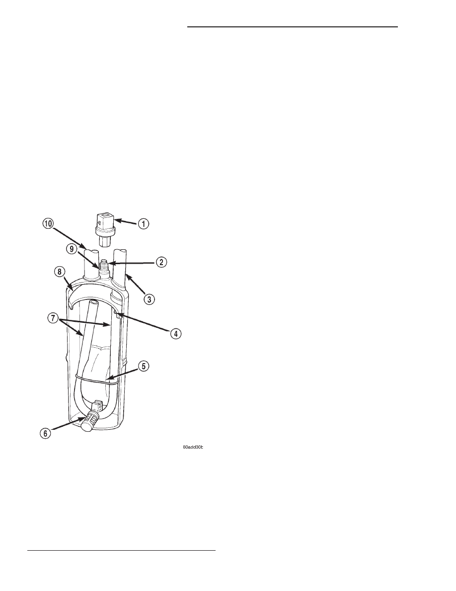
ACCUMULATOR
DESCRIPTION
The accumulator is mounted in the engine com-
partment between the evaporator coil outlet tube and
the compressor inlet.
OPERATION
Refrigerant enters the accumulator canister as a
low pressure vapor through the inlet tube. Any liq-
uid, oil-laden refrigerant falls to the bottom of the
canister, which acts as a separator. A desiccant bag is
mounted inside the accumulator canister to absorb
any moisture which may have entered and become
trapped within the refrigerant system (Fig. 1).
BLOWER MOTOR
DESCRIPTION
The blower motor and blower wheel are located in
the passenger side end of the heater-A/C housing,
below the glove box module. The blower motor con-
trols the velocity of the air flowing through the heat-
er-A/C housing by spinning a squirrel cage-type
blower wheel within the housing at the selected
speed. The blower motor and blower wheel can be
serviced from the passenger compartment side of the
housing.
OPERATION
The blower motor will only operate when the igni-
tion switch is in the On position, and the heater-A/C
mode control switch is in any position, except Off.
The blower motor circuit is protected by a fuse in the
junction block. On models with the standard manual
temperature control system, the blower motor speed
is controlled by regulating the battery feed through
the blower motor switch and the blower motor resis-
tor. On models with the optional Automatic Zone
Control (AZC) system, the blower motor speed is con-
trolled by using Pulse Width Modulation (PWM). The
power module adjusts the battery feed voltage to the
blower motor, based upon an input from the blower
motor switch, through the AZC control module. Pulse
width modulation of blower power allows the blower
to operate at any speed from stationary, to full speed.
The blower motor and blower motor wheel cannot
be repaired, and if faulty or damaged, they must be
replaced. The blower motor and blower wheel are
each serviced separately.
BLOWER MOTOR CONTROLLER
DESCRIPTION
Models equipped with the optional Automatic Zone
Control (AZC) system have a blower motor controller
(power module). The controller allows the selection of
almost infinitely variable blower motor speeds. The
controller is mounted to the heater-A/C housing,
under the instrument panel and just inboard of the
blower motor, in the same location used for the
blower motor resistor on manual temperature control
systems. It can be accessed without removing any
other components.
OPERATION
The blower motor controller output to the blower
motor can be adjusted by the blower motor speed
switch knob on the AZC heater-A/C control panel, or
it can be adjusted automatically by the logic circuitry
and programming of the AZC control module. In
either case, the AZC control module sends the correct
Fig. 1 Accumulator - Typical
1 – LOW PRESSURE CYCLING CLUTCH SWITCH
2 – PRESSURE SWITCH FITTING
3 – OUTLET TO COMPRESSOR
4 – ANTI-SIPHON HOLE
5 – DESICCANT BAG
6 – OIL RETURN ORIFICE FILTER
7 – VAPOR RETURN TUBE
8 – ACCUMULATOR DOME
9 – O-RING SEAL
10 – INLET FROM EVAPORATOR
24 - 2
HEATING AND AIR CONDITIONING
WJ