Jeep Grand Cherokee WJ. Manual - part 491


  Index      Jeep     Jeep Grand Cherokee WJ - service repair manual 2001 year


Search            


Content   ..  489  490  491  492   ..


Jeep Grand Cherokee WJ. Manual - part 491


(9) Return to shop or move vehicle off chassis

dyno.

AIR TESTING TRANSMISSION CLUTCH AND
BAND OPERATION

Air-pressure testing can be used to check transmis-

sion front/rear clutch and band operation. The test
can be conducted with the transmission either in the
vehicle or on the work bench, as a final check, after
overhaul.

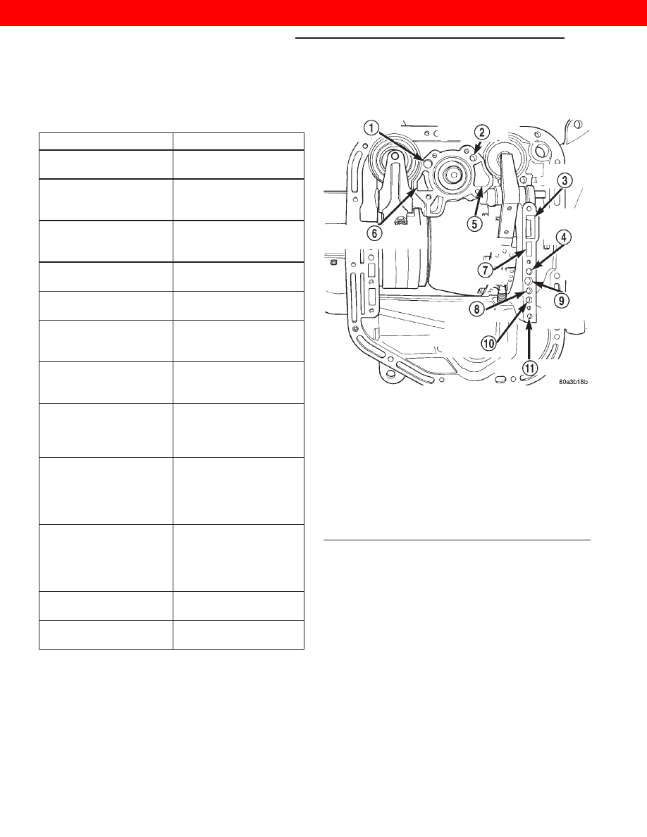
Air-pressure testing requires that the oil pan and

valve body be removed from the transmission. The
servo and clutch apply passages are shown (Fig. 8).

Front Clutch Air Test

Place one or two fingers on the clutch housing and

apply air pressure through front clutch apply pas-
sage. Piston movement can be felt and a soft thump
heard as the clutch applies.

Rear Clutch Air Test

Place one or two fingers on the clutch housing and

apply air pressure through rear clutch apply passage.
Piston movement can be felt and a soft thump heard
as the clutch applies.

Front Servo Apply Air Test

Apply air pressure to the front servo apply pas-

sage. The servo rod should extend and cause the
band to tighten around the drum. Spring pressure
should release the servo when air pressure is
removed.

PRESSURE TEST ANALYSIS CHART

TEST CONDITION

INDICATION

Line pressure OK during
any one test

Pump and regulator
valve OK

Line pressure OK in R
but low in D, 2, 1

Leakage in rear clutch
area (seal rings, clutch
seals)

Pressure low in D Fourth
Gear Range

Overdrive clutch piston
seal, or check ball
problem

Pressure OK in 1, 2 but
low in D3 and R

Leakage in front clutch
area

Pressure OK in 2 but low
in R and 1

Leakage in rear servo

Front servo pressure low
in 2

Leakage in servo; broken
servo ring or cracked
servo piston

Pressure low in all
positions

Clogged filter, stuck
regulator valve, worn or
faulty pump, low oil level

Governor pressure too
high at idle speed

Governor pressure
solenoid valve system
fault. Refer to diagnostic
book.

Governor pressure low at
all mph figures

Faulty governor pressure
solenoid, transmission
control module, or
governor pressure
sensor

Lubrication pressure low
at all throttle positions

Clogged fluid cooler or
lines, seal rings leaking,
worn pump bushings,
pump, clutch retainer, or
clogged filter.

Line pressure high

Output shaft plugged,
sticky regulator valve

Line pressure low

Sticky regulator valve,
clogged filter, worn pump

Fig. 8 Air Pressure Test Passages

1 – REAR SERVO APPLY
2 – FRONT SERVO APPLY
3 – PUMP SUCTION
4 – FRONT CLUTCH APPLY
5 – FRONT SERVO RELEASE
6 – LINE PRESSURE TO ACCUMULATOR
7 – PUMP PRESSURE
8 – TO CONVERTER
9 – REAR CLUTCH APPLY
10 – FROM CONVERTER
11 – TO COOLER

21 - 14

TRANSMISSION AND TRANSFER CASE

WJ

DIAGNOSIS AND TESTING (Continued)

2000 JEEP GRAND CHEROKEE

Rear Servo Air Test

Apply air pressure to the rear servo apply passage.

The servo rod should extend and cause the band to
tighten around the drum. Spring pressure should
release the servo when air pressure is removed.

CONVERTER HOUSING FLUID LEAK
DIAGNOSIS

When diagnosing converter housing fluid leaks,

three items must be established before repair.

(1) Verify the correct fluid level in the transmis-

sion.

(2) Verify that a leak condition actually exists.
(3) Determined the true source of the leak.
Some suspected converter housing fluid leaks may

not be leaks at all. They may only be the result of
residual fluid in the converter housing, excessive
fluid fill or excess fluid spilled during factory fill or
fill after repair. Converter housing leaks have several
potential sources. Through careful observation, a leak
source can be identified before removing the trans-
mission for repair. Pump seal leaks tend to move
along the drive hub and onto the rear of the con-
verter. Pump O-ring or pump body leaks follow the
same path as a seal leak (Fig. 9). Pump vent or
pump attaching bolt leaks are generally deposited on
the inside of the converter housing and not on the
converter itself (Fig. 9). Pump seal or gasket leaks
usually travel down the inside of the converter hous-
ing. Front band lever pin plug leaks are generally
deposited on the housing and not on the converter.

TORQUE CONVERTER LEAK POINTS

Possible sources of converter leaks are:
(1) Leaks at the weld joint around the outside

diameter weld (Fig. 10).

(2) Leaks at the converter hub weld (Fig. 10).

CONVERTER HOUSING AREA LEAK CORRECTION

(1) Remove the transmission and torque converter.

Refer to the procedure in this group.

(2) Tighten front band adjusting screw until band

is tight around front clutch retainer. This prevents
front/rear clutches from coming out when oil pump is
removed.

(3) Remove oil pump and remove pump seal.

Inspect pump housing drainback and vent holes for
obstructions. Clear holes with solvent and wire.

(4) Inspect pump bushing and converter hub. If

bushing is scored, replace it. If converter hub is
scored, either polish it with crocus cloth or replace
converter.

(5) Install new pump seal, O-ring, and gasket.

Replace oil pump if cracked, porous or damaged in
any way. Be sure to loosen the front band before
installing the oil pump, damage to the oil pump seal
rings may occur if the band is still tightened to the
front clutch retainer.

(6) Loosen kickdown lever pin access plug three

turns. Apply Loctite 592, or Permatex No. 2 to plug
threads and tighten plug to 17 N·m (150 in. lbs.)
torque.

(7) Adjust front band.
(8) Lubricate pump seal and converter hub with

transmission fluid or petroleum jelly and install con-
verter.

(9) Install transmission and converter housing

dust shield.

(10) Lower vehicle.

Fig. 9 Converter Housing Leak Paths

1 – PUMP SEAL
2 – PUMP VENT
3 – PUMP BOLT
4 – PUMP GASKET
5 – CONVERTER HOUSING
6 – CONVERTER
7 – REAR MAIN SEAL LEAK

Fig. 10 Converter Leak Points—Typical

1 – OUTSIDE DIAMETER WELD
2 – TORQUE CONVERTER HUB WELD
3 – STARTER RING GEAR
4 – LUG

WJ

TRANSMISSION AND TRANSFER CASE

21 - 15

DIAGNOSIS AND TESTING (Continued)

2000 JEEP GRAND CHEROKEE

DIAGNOSIS TABLES AND CHARTS—RE
TRANSMISSION

The diagnosis charts provide additional reference

when diagnosing a transmission fault. The charts pro-
vide general information on a variety of transmission,
overdrive unit and converter clutch fault conditions.

The hydraulic flow charts in the Schematics and

Diagrams section of this group, outline fluid flow and
hydraulic circuitry. Circuit operation is provided for
neutral, third, fourth and reverse gear ranges. Nor-
mal working pressures are also supplied for each of
the gear ranges.

DIAGNOSIS CHARTS

CONDITION

POSSIBLE CAUSES

CORRECTION

HARSH ENGAGEMENT
(FROM NEUTRAL TO
DRIVE OR REVERSE)

1. Fluid Level Low

1. Add Fluid

2. Throttle Linkage Misadjusted

2. Adjust linkage - setting may be too long.

3. Mount and Driveline Bolts
Loose

3. Check engine mount, transmission mount,
propeller shaft, rear spring to body bolts, rear
control arms, crossmember and axle bolt
torque. Tighten loose bolts and replace
missing bolts.

4. U-Joint Worn/Broken

4. Remove propeller shaft and replace U-Joint.

5. Axle Backlash Incorrect

5. Check per Service Manual. Correct as
needed.

6. Hydraulic Pressure Incorrect

6. Check pressure. Remove, overhaul or
adjust valve body as needed.

7. Band Misadjusted.

7. Adjust rear band.

8. Valve Body Check Balls
Missing.

8. Inspect valve body for proper check ball
installation.

9. Axle Pinion Flange Loose.

9. Replace nut and check pinion threads
before installing new nut. Replace pinion gear
if threads are damaged.

10. Clutch, band or planetary
component damaged.

10. Remove, disassemble and repair
transmission as necessary.

11. Converter Clutch Faulty.

11. Replace converter and flush cooler and
line before installing new converter.

21 - 16

TRANSMISSION AND TRANSFER CASE

WJ

DIAGNOSIS AND TESTING (Continued)

2000 JEEP GRAND CHEROKEE

CONDITION

POSSIBLE CAUSES

CORRECTION

DELAYED ENGAGEMENT
(FROM NEUTRAL TO
DRIVE OR REVERSE)

1. Fluid Level Low.

1. Correct level and check for leaks.

2. Filter Clogged.

2. Change filter.

3. Gearshift Linkage Misadjusted.

3. Adjust linkage and repair linkage if worn or
damaged.

4. Torque Converter Drain Back
(Oil drains from torque converter
into transmission sump)

4. If vehicle moves normally after 5 seconds
after shifting into gear, no repair is necessary.
If longer, inspect pump bushing for wear.
Replace pump house.

5. Rear Band Misadjusted.

5. Adjust band.

6. Valve Body Filter Plugged.

6. Replace fluid and filter. If oil pan and old
fluid were full of clutch disc material and/or
metal particles, overhaul will be necessary.

7. Oil Pump Gears Worn/
Damaged.

7. Remove transmission and replace oil pump.

8. Governor Circuit and Solenoid
Valve Electrical Fault.

8. Test with DRB scan tool and repair as
required.

9. Hydraulic Pressure Incorrect.

9. Perform pressure test, remove transmission
and repair as needed.

10. Reaction Shaft Seal Rings
Worn/Broken.

10. Remove transmission, remove oil pump
and replace seal rings.

11. Rear Clutch/Input Shaft, Rear
Clutch Seal Rings Damaged.

11. Remove and disassemble transmission
and repair as necessary.

12. Regulator Valve Stuck.

12. Clean.

13. Cooler Plugged.

13. Transfer case failure can plug cooler.

NO DRIVE RANGE
(REVERSE OK)

1. Fluid Level Low.

1. Add fluid and check for leaks if drive is
restored.

2. Gearshift Linkage/Cable
Loose/Misadjusted.

2. Repair or replace linkage components.

3. Rear Clutch Burnt.

3. Remove and disassemble transmission and
rear clutch and seals. Repair/replace worn or
damaged parts as needed.

4. Valve Body Malfunction.

4. Remove and disassemble valve body.
Replace assembly if any valves or bores are
damaged.

5. Transmission Overrunning
Clutch Broken.

5. Remove and disassemble transmission.
Replace overrunning clutch.

6. Input Shaft Seal Rings
Worn/Damaged.

6. Remove and disassemble transmission.
Replace seal rings and any other worn or
damaged parts.

7. Front Planetary Failed Broken.

7. Remove and repair.

WJ

TRANSMISSION AND TRANSFER CASE

21 - 17

DIAGNOSIS AND TESTING (Continued)

2000 JEEP GRAND CHEROKEE


Content   ..  489  490  491  492   ..