Jeep Grand Cherokee WJ. Manual - part 467
(5) Shifting out of park should not be possible
when the ignition key cylinder is in the accessory or
lock position.
(6) Shifting between any gears neutral or park
may be done without depressing foot brake with igni-
tion switch in run or start positions and vehicle sta-
tionary or in motion.
(7) The floor shifter lever and gate positions
should be in alignment with all transmission detent
positions.
(8) Engine starts must be possible with shifter
lever in park or neutral gate positions only. Engine
starts must not be possible in any other gate posi-
tions other than park or neutral.
(9) With shifter lever handle push-button not
depressed and lever detent in:
• PARK POSITION- apply forward force on center
of handle and remove pressure. Engine start must be
possible.
• PARK POSITION- apply rearward force on cen-
ter of handle and remove pressure. Engine start
must be possible.
• NEUTRAL POSITION- engine start must be
possible.
• NEUTRAL POSITION, ENGINE RUNNING
AND BRAKES APPLIED- Apply forward force on
center of shift handle. Transmission should not be
able to shift into reverse detent.
GEARSHIFT CABLE
Check adjustment by starting the engine in Park
and Neutral. Adjustment is OK if the engine starts
only in these positions. Adjustment is incorrect if the
engine starts in one but not both positions. If the
engine starts in any position other than Park or Neu-
tral, or if the engine will not start at all, the park/
neutral position switch or TRS may be faulty.
Gearshift Adjustment Procedure
(1) Shift transmission into Park.
(2) Remove shift lever bezel and floor console as
necessary for access to the shift cable adjustment.
(3) Loosen the shift cable adjustment screw (Fig.
127).
(4) Raise vehicle.
(5) Unsnap cable eyelet from transmission shift
lever (Fig. 128).
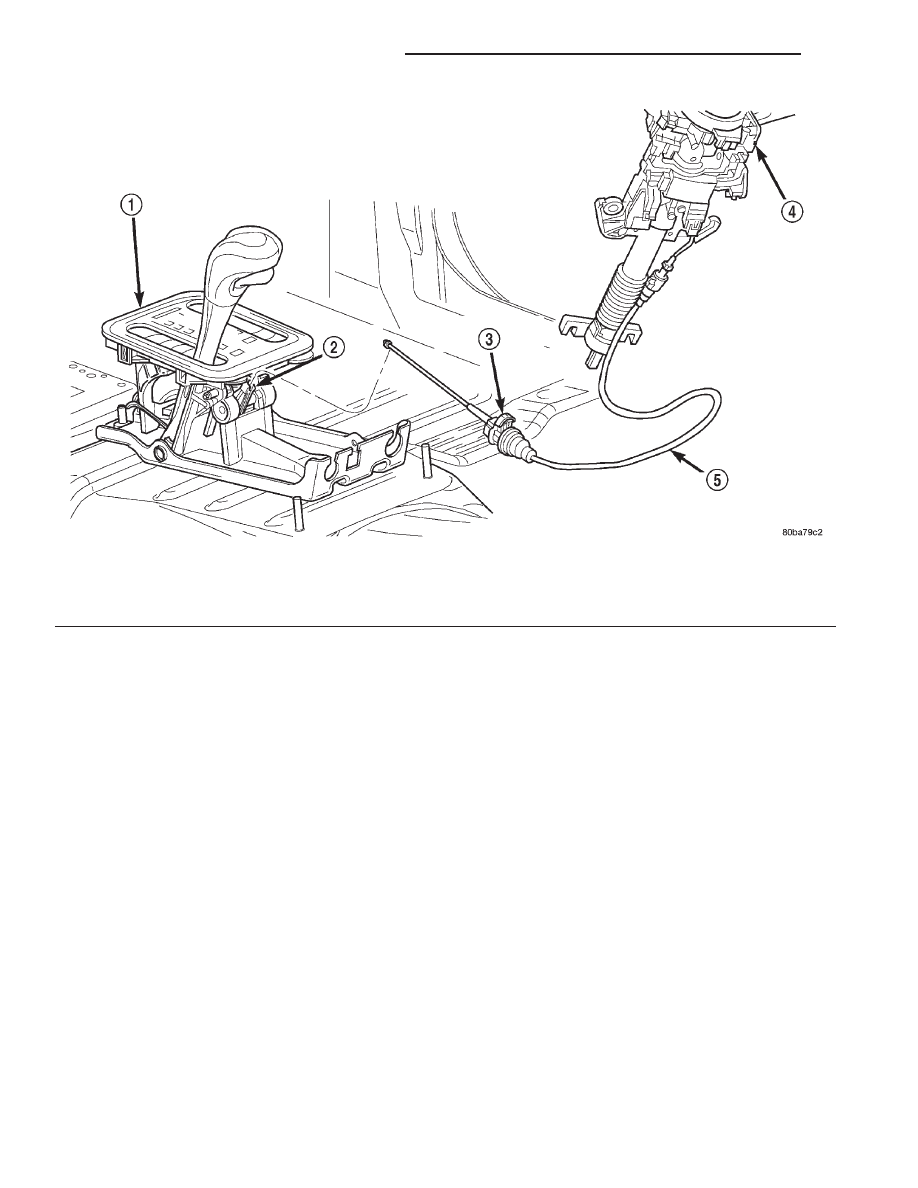
Fig. 126 Brake Transmission Shift Interlock Cable
1 – SHIFT MECHANISM
2 – SHIFTER BTSI LEVER
3 – ADJUSTMENT CLIP
4 – STEERING COLUMN ASSEMBLY
5 – INTERLOCK CABLE
21 - 250
45RFE AUTOMATIC TRANSMISSION
WJ
ADJUSTMENTS (Continued)