Jeep Grand Cherokee WJ. Manual - part 466


  Index      Jeep     Jeep Grand Cherokee WJ - service repair manual 2001 year


Search            


Content   ..  464  465  466  467   ..


Jeep Grand Cherokee WJ. Manual - part 466


(8) Remove the overrunning clutch lower snap-ring

(Fig. 122).

(9) Using Spring Compressor 8285 and a suitable

shop press (Fig. 123), compress the low/reverse pis-
ton Belleville spring and remove the split retaining
ring holding the Belleville spring into the low/reverse
clutch retainer.

(10) Remove

the

low/reverse

clutch

Belleville

spring

and

piston

from

the

low/reverse

clutch

retainer. Use 20 psi of air pressure to remove the pis-
ton if necessary.

ASSEMBLY

(1) Clean and inspect all components. Replace any

components which show evidence of excessive wear
or scoring.

(2) Check the bleed orifice to ensure that it is not

plugged or restricted.

(3) Install a new seal on the low/reverse piston.

Lubricate the seal with Mopar

t ATF+3, type 7176

prior to installation.

(4) Install the low/reverse piston into the low/re-

verse clutch retainer.

(5) Position the low/reverse piston Belleville spring

on the low/reverse piston.

(6) Using Spring Compressor 8285 and a suitable

shop press (Fig. 123), compress the low/reverse pis-
ton Belleville spring and install the split retaining
ring to hold the Belleville spring into the low/reverse
clutch retainer.

(7) Install the lower overrunning clutch snap-ring

(Fig. 122).

(8) Assemble the inner and outer races of the over-

running clutch (Fig. 122).

(9) Position the overrunning clutch spacer on the

overrunning clutch.

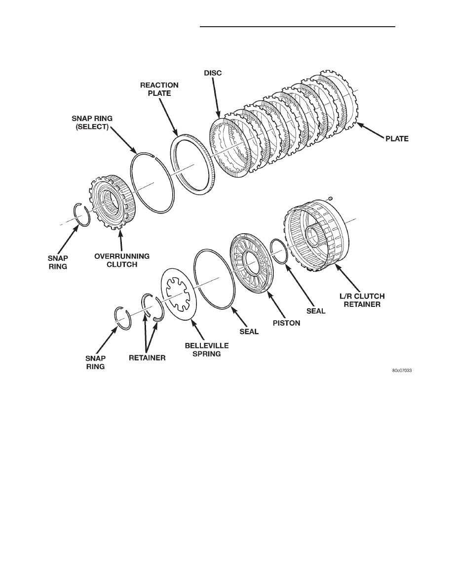
Fig. 121 Low/Reverse Clutch Assembly

21 - 246

45RFE AUTOMATIC TRANSMISSION

WJ

DISASSEMBLY AND ASSEMBLY (Continued)

(10) Install the upper overrunning clutch snap-

ring (Fig. 122).

(11) Assemble and install the low/reverse clutch

pack into the low/reverse clutch retainer (Fig. 121).

(12) Install the low/reverse reaction plate into the

low/reverse clutch retainer (Fig. 121). The reaction
plate is directional and must be installed with the
flat side down.

(13) Install the low/reverse clutch pack snap-ring

(Fig. 121). The snap-ring is selectable and should be
chosen to give the correct clutch pack clearance.

(14) Measure the low/reverse clutch pack clearance

and adjust as necessary. The correct clutch clearance
is 1.14–1.91 mm (0.045–0.05 in.).

(15) Install the overrunning clutch into the low/re-

verse clutch retainer making sure that the index
splines are aligned with the retainer.

(16) Install the overrunning clutch inner snap-

ring.

CLEANING AND INSPECTION

VALVE BODY

Clean the valve housings, valves, plugs, springs,

and separator plates with a standard parts cleaning
solution only. Do not use gasoline, kerosene, or any
type of caustic solution.

Do not immerse any of the electrical components in

cleaning solution. Clean the electrical components by
wiping them off with dry shop towels only.

Dry all except the electrical parts with compressed

air. Make sure all passages are clean and free from
obstructions. Do not use rags or shop towels to
dry or wipe off valve body components. Lint
from these materials can stick to valve body
parts, interfere with valve operation, and clog
filters and fluid passages.

Inspect all of the valve body mating surfaces for

scratches, nicks, burrs, or distortion. Use a straight-
edge to check surface flatness. Minor scratches may
be removed with crocus cloth using only very light
pressure.

Minor distortion of a valve body mating surface

may be corrected by smoothing the surface with a
sheet of crocus cloth. Position the crocus cloth on a
surface plate, sheet of plate glass or equally flat sur-
face. If distortion is severe or any surfaces are
heavily scored, the valve body will have to be
replaced.

Inspect

the

valves

and

plugs

(Fig.

124)

for

scratches, burrs, nicks, or scores. Minor surface
scratches on steel valves and plugs can be removed
with crocus cloth but do not round off the edges
of the valve or plug lands. 
Maintaining sharpness
of these edges is vitally important. The edges prevent
foreign matter from lodging between the valves and
plugs and the bore.

Inspect all the valve and plug bores in the valve

body. Use a penlight to view the bore interiors.
Replace the valve body if any bores are distorted or
scored. Inspect all of the valve body springs. The
springs must be free of distortion, warpage or broken
coils.

Trial fit each valve and plug in its bore to check

freedom of operation. When clean and dry, the valves
and plugs should drop freely into the bores.

Valve body bores do not change dimensionally with

use. If the valve body functioned correctly when new,
it will continue to operate properly after cleaning and
inspection. It should not be necessary to replace a

Fig. 122 Overrunning Clutch

Fig. 123 Compress Low/Reverse Belleville Spring

Using Tool 8285

WJ

45RFE AUTOMATIC TRANSMISSION

21 - 247

DISASSEMBLY AND ASSEMBLY (Continued)

valve body assembly unless it is damaged in han-
dling.

Inspect all the accumulator bores in the valve body.

Use a penlight to view the bore interiors. Replace the
valve body if any bores are distorted or scored.
Inspect all of the accumulator springs. The springs
must be free of distortion, warpage or broken coils.

Inspect all the fluid seals on the valve body (Fig.

125). Replace any seals that are cracked, distorted, or
damaged in any way. These seals pass fluid pressure
directly to the clutches. Any pressure leak at these
points, may cause transmission performance prob-
lems.

TRANSMISSION

GENERAL INFORMATION

Heli-Coil inserts can be used to repair damaged,

stripped or worn threads in aluminum parts. These
inserts are available from most automotive parts
suppliers. Stainless steel inserts are recommended.

The use of crocus cloth is permissible where neces-

sary, providing it is used carefully. When used on
shafts, or valves, use extreme care to avoid rounding
off sharp edges. Sharp edges are vital as they pre-
vent foreign matter from getting between the valve
and valve bore.

Do not reuse oil seals, gaskets, seal rings, or

O-rings during overhaul. Replace these parts as a
matter of course. Also do not reuse snap rings or
E-clips that are bent or distorted. Replace these parts
as well.

Lubricate transmission parts with Mopar

t ATF

Plus 3, Type 7176, transmission fluid during over-
haul and assembly. Use petroleum jelly, Mopar

t Door

Ease, or Ru-Glyde to prelubricate seals, O-rings, and
thrust washers. Petroleum jelly can also be used to
hold parts in place during reassembly.

TRANSMISSION CASE CLEANING AND
INSPECTION

Clean the case in a solvent tank. Flush the case

bores and fluid passages thoroughly with solvent.
Dry the case and all fluid passages with compressed
air. Be sure all solvent is removed from the case and
that all fluid passages are clear.

NOTE: Do not use shop towels or rags to dry the
case (or any other transmission component) unless
they are made from lint-free materials. Lint will stick
to case surfaces and transmission components and
circulate throughout the transmission after assem-
bly. A sufficient quantity of lint can block fluid pas-
sages and interfere with valve body operation.

Inspect the case for cracks, porous spots, worn

bores, or damaged threads. Damaged threads can be
repaired with Helicoil thread inserts. However, the
case will have to be replaced if it exhibits any type of
damage or wear.

Fig. 124 Valve Body Components

Fig. 125 Valve Body Seals

21 - 248

45RFE AUTOMATIC TRANSMISSION

WJ

CLEANING AND INSPECTION (Continued)

LOW/REVERSE CLUTCH ASSEMBLY

Clean the overrunning clutch assembly, clutch cam,

and low-reverse clutch retainer. Dry them with com-
pressed air after cleaning.

Inspect condition of each clutch part after cleaning.

Replace the overrunning clutch roller and spring
assembly if any rollers or springs are worn or dam-
aged, or if the roller cage is distorted, or damaged.
Replace the cam if worn, cracked or damaged.

Replace the low-reverse clutch retainer if the

clutch race, roller surface or inside diameter is
scored, worn or damaged.

ACCUMULATOR

Inspect the accumulator piston and seal rings.

Replace the seal rings if worn or cut. Replace the pis-
ton if chipped or cracked.

Check condition of the accumulator inner and

outer springs. Replace the springs if the coils are
cracked, distorted or collapsed.

OIL PUMP AND REACTION SHAFT SUPPORT

Clean pump and support components with solvent

and dry them with compressed air.

Check condition of the seal rings and thrust

washer on the reaction shaft support. The seal rings
do not need to be replaced unless cracked, broken, or
severely worn.

Inspect the pump and support components. Replace

the pump or support if the seal ring grooves or
machined surfaces are worn, scored, pitted, or dam-
aged. Replace the pump gears if pitted, worn
chipped, or damaged.

Inspect the pump bushing. Then check the reaction

shaft support bushing. Replace either bushing only if
heavily worn, scored or damaged. It is not necessary
to replace the bushings unless they are actually dam-
aged.

Inspect the valves and plugs for scratches, burrs,

nicks, or scores. Minor surface scratches on steel
valves and plugs can be removed with crocus cloth
but do not round off the edges of the valve or
plug lands. 
Maintaining sharpness of these edges is
vitally important. The edges prevent foreign matter
from lodging between the valves and plugs and the
bore.

Inspect all the valve and plug bores in the oil

pump cover. Use a penlight to view the bore interi-
ors. Replace the oil pump if any bores are distorted
or scored. Inspect all of the valve springs. The
springs must be free of distortion, warpage or broken
coils.

Trial fit each valve and plug in its bore to check

freedom of operation. When clean and dry, the valves
and plugs should drop freely into the bores.

PLANETARY GEARTRAIN

Clean the planetary components in solvent and dry

them with compressed air.

Check

sun

gear

and

driving

shell

condition.

Replace the gear if damaged or if the bushings are
scored or worn. The bushings are not serviceable.
Replace the driving shell if worn, cracked or dam-
aged.

Replace planetary gear sets if gears, pinion pins, or

carrier are damaged in any way. Replace the annulus
gears and supports if either component is worn or
damaged.

Replace the output shaft if the machined surfaces

are scored, pitted, or damaged in any way. Also
replace the shaft if the splines are damaged, or
exhibits cracks at any location.

ADJUSTMENTS

BRAKE TRANSMISSION SHIFT INTERLOCK

The park interlock cable is part of the brake/shift

lever interlock system. Correct cable adjustment is
important to proper interlock operation. The gear
shift and park lock cables must both be correctly
adjusted in order to shift out of Park.

Park Interlock Cable Adjustment Procedure

(1) Shift the transmission into the PARK position.
(2) Turn ignition switch to LOCK position. Be

sure ignition key cylinder is in the LOCK posi-
tion. Cable will not adjust correctly in any
other position.

(3) Remove shift lever bezel and floor console as

necessary for access to the brake transmission shift
interlock cable.

(4) Pull cable lock button up to release cable (Fig.

126).

(5) Pull cable rearward. Then release cable and

press lock button down until it snaps in place.

BTSI FUNCTION CHECK

(1) Verify removal of ignition key allowed in park

position only.

(2) When the shift lever is in park, and the shift

handle push-button is in the out position, the igni-
tion key cylinder should rotate freely from off to lock.
When the shifter is in any other position, the ignition
key should not rotate from off to lock.

(3) Shifting out of park should be possible when

the ignition key cylinder is in the off position.

(4) Shifting out of park should not be possible

while applying 25 lb. max. handle push-button force,
and ignition key cylinder is in the run or start posi-
tions, unless the foot brake pedal is depressed
approximately 1/2 inch (12 mm).

WJ

45RFE AUTOMATIC TRANSMISSION

21 - 249

CLEANING AND INSPECTION (Continued)


Content   ..  464  465  466  467   ..