Jeep Grand Cherokee WJ. Manual - part 465


  Index      Jeep     Jeep Grand Cherokee WJ - service repair manual 2001 year


Search            


Content   ..  463  464  465  466   ..


Jeep Grand Cherokee WJ. Manual - part 465


ment in four (4) places, 90° apart. Take average of
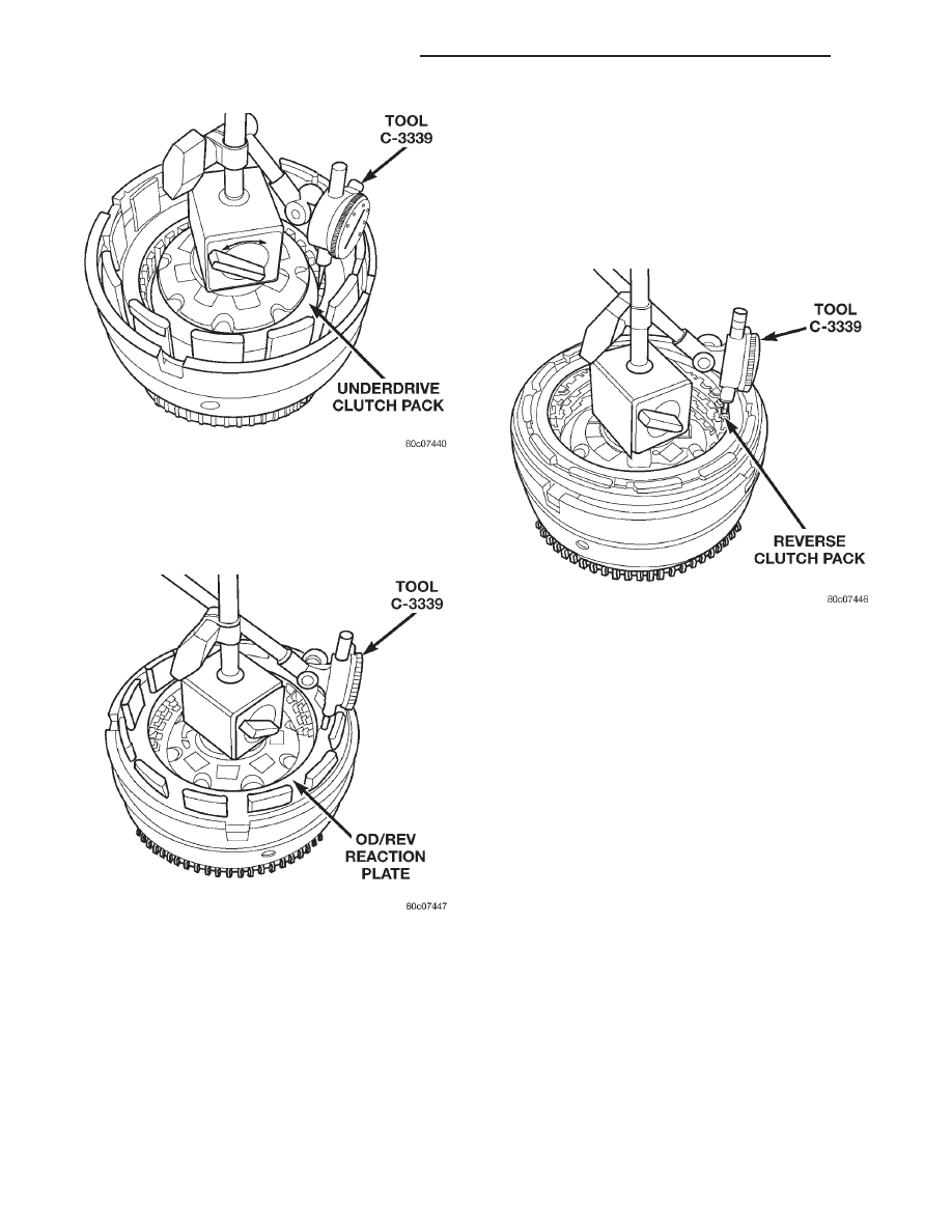
four measurements and compare with OD clutch
pack clearance specification.Verify that the clutch
clearance is 1.016–1.65 mm (0.040–0.065 in.).

(22) Install the reverse clutch pack into the input

clutch retainer (Fig. 107).

(23) Install the reverse reaction plate into the

input clutch retainer.

(24) Install the reverse reaction plate selective

snap-ring into the input clutch retainer.

(25) Mount a dial indicator to the assembly, push

down on the clutch discs, pull up on the reaction
planetary plate to ensure the plate is properly seated
and zero the indicator against the reverse clutch
discs (Fig. 116). Apply 20 psi of air pressure to the

reverse clutch and record the dial indicator reading.
Measure and record Reverse clutch pack measure-
ment in four (4) places, 90° apart. Take average of
four measurements and compare with Reverse clutch
pack clearance specification. The correct clutch clear-
ance is 0.81–1.24 mm (0.032–0.049 in.). Adjust as
necessary. Install the chosen snap-ring and re-mea-
sure to verify selection.

(26) Remove the reverse clutch pack from the

input clutch retainer.

(27) Install the number 2 bearing onto the under-

drive hub with flat side up/forward with petroleum
jelly.

(28) Install the underdrive hub into the input

clutch retainer.

(29) Install the number 3 bearing into the over-

drive hub with the flat side up/forward with petro-
leum jelly.

(30) Install the overdrive hub into the input clutch

retainer.

(31) Install the number 4 bearing into the reverse

hub with flat side up/forward with petroleum jelly.

(32) Install the reverse hub into the input clutch

retainer.

(33) Install the complete reverse clutch pack.
(34) Install the reverse reaction plate and snap-

ring.

(35) Push up on reaction plate to allow reverse

clutch to move freely.

4C RETAINER/BULKHEAD

DISASSEMBLY

(1) Remove the 2C piston belleville spring snap-

ring from the 4C retainer/bulkhead (Fig. 117).

Fig. 114 Measuring UD Clutch Clearance

Fig. 115 Measuring OD Clutch Clearance

Fig. 116 Measuring Reverse Clutch Clearance

21 - 242

45RFE AUTOMATIC TRANSMISSION

WJ

DISASSEMBLY AND ASSEMBLY (Continued)

(2) Remove the 2C piston Belleville spring from

the retainer/bulkhead (Fig. 117).

(3) Remove the 2C piston from the retainer/bulk-

head. Use 20 psi of air pressure to remove the piston
if necessary.

(4) Remove the 4C clutch snap-ring from the

retainer/bulkhead (Fig. 117).

(5) Remove the 4C clutch pack from the retainer/

bulkhead (Fig. 117).

(6) Using Spring Compressor 8250 and a suitable

shop press, compress the 4C piston return spring and
remove the snap-ring (Fig. 117).

(7) Remove the 4C piston return spring and piston

from the retainer/bulkhead (Fig. 117). Use 20 psi of
air pressure to remove the piston if necessary.

ASSEMBLY

(1) Clean and inspect all components. Replace any

components which show evidence of excessive wear
or scoring.

(2) Install new seals on the 2C and 4C pistons

(Fig. 117).

(3) Lubricate all seals with Mopar

t ATF+3, type

7176 prior to installation.

(4) Install the 4C piston into the 4C retainer/bulk-

head (Fig. 117).

(5) Position the 4C piston return spring onto the

4C piston.

(6) Using Spring Compressor 8250 and a suitable

shop press, compress the 4C piston return spring and
install the snap-ring (Fig. 118).

(7) Assemble and install the 4C clutch pack into

the retainer/bulkhead (Fig. 117).

(8) Install the 4C reaction plate and snap-ring into

the retainer/bulkhead (Fig. 117). The 4C reaction
plate is non-directional.

(9) Measure the 4C clutch clearance. The correct

clutch clearance is 0.81–1.35 mm (0.032–0.053 in.).
The snap-ring is selectable. Install the chosen snap-
ring and re-measure to verify the selection.

(10) Install the 2C piston into the retainer/bulk-

head (Fig. 117).

(11) Position the 2C Belleville spring onto the 2C

piston.

(12) Position the 2C Belleville spring snap-ring

onto the 2C Belleville spring (Fig. 117).

(13) Using Spring Compressor 8249 and a suitable

shop press (Fig. 119), compress the belleville spring

Fig. 117 4C Retainer/Bulkhead Components

WJ

45RFE AUTOMATIC TRANSMISSION

21 - 243

DISASSEMBLY AND ASSEMBLY (Continued)

until the snap-ring is engaged with the snap-ring
groove in the retainer/bulkhead.

PLANETARY GEAR SET

DISASSEMBLY

(1) Remove the snap-ring holding the input annu-

lus into the input carrier (Fig. 120).

(2) Remove the input annulus from the input car-

rier (Fig. 120).

(3) Remove the number 9 bearing from the reverse

planetary carrier. Note that this planetary carrier
has four pinion gears.

(4) Remove the reverse planetary gear carrier (Fig.

120).

(5) Remove the number 10 bearing from the input

sun gear (Fig. 120).

(6) Remove the input sun gear from the input car-

rier (Fig. 120).

(7) Remove the number 11 bearing from the input

carrier (Fig. 120).

ASSEMBLY

(1) Clean and inspect all components. Replace any

components which show evidence of excessive wear
or scoring.

(2) Install the number 11 bearing into the input

planetary carrier with the flat side up and facing for-
ward (Fig. 120).

(3) Install the input sun gear into the input carrier

(Fig. 120).

(4) Install the number 10 bearing onto the rear of

the reverse planetary carrier with the flat side
toward the carrier (Fig. 120).

(5) Install the number 9 bearing onto the front of

the reverse planetary carrier with the rounded side
toward the carrier and the flat side facing upward
(Fig. 120).

(6) Install the reverse planetary gear carrier into

the input carrier (Fig. 120).

(7) Install the input annulus gear into the input

carrier (Fig. 120).

(8) Install the snap-ring to hold the input annulus

gear into the input carrier (Fig. 120).

Fig. 118 Compress 4C Piston Return Spring Using

Tool 8250

Fig. 119 Compress 2C Belleville Spring Using Tool

8249

21 - 244

45RFE AUTOMATIC TRANSMISSION

WJ

DISASSEMBLY AND ASSEMBLY (Continued)

LOW/REVERSE CLUTCH

DISASSEMBLY

(1) Remove the inner overrunning clutch snap-ring

from the low/reverse clutch retainer (Fig. 121).

(2) Remove the outer low/reverse reaction plate

flat snap-ring (Fig. 121).

(3) Remove the low/reverse clutch and the over-

running clutch from the low/reverse clutch retainer
as an assembly (Fig. 121).

(4) Separate the low/reverse clutch from the over-

running clutch.

(5) Remove the overrunning clutch snap-ring (Fig.

122).

(6) Remove the spacer from the overrunning clutch

(Fig. 122).

(7) Separate the inner and outer races of the over-

running clutch (Fig. 122).

Fig. 120 Reverse/Input Planetary Carrier Assembly

WJ

45RFE AUTOMATIC TRANSMISSION

21 - 245

DISASSEMBLY AND ASSEMBLY (Continued)


Content   ..  463  464  465  466   ..