Jeep Grand Cherokee WJ. Manual - part 463


  Index      Jeep     Jeep Grand Cherokee WJ - service repair manual 2001 year


Search            


Content   ..  461  462  463  464   ..


Jeep Grand Cherokee WJ. Manual - part 463


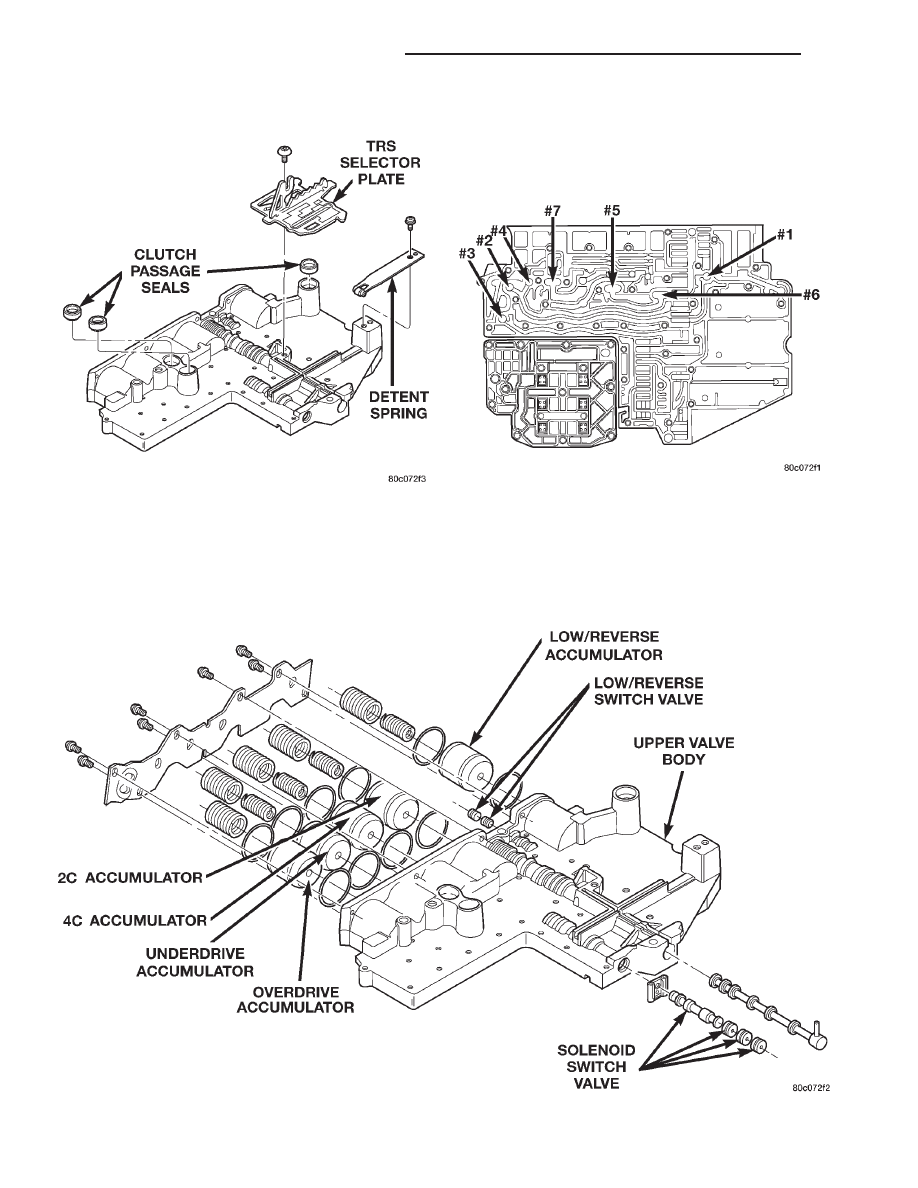
NOTE: The valve body contains seven check balls.
The transfer plate must be placed upward to pre-
vent losing the check balls when the transfer plate
is removed from the valve body.

(10) Remove the screws holding the valve body to

the valve body transfer plate.

(11) Remove the transfer plate from the valve

body. Note the location of all check balls (Fig. 101).

(12) Remove the check balls from the valve body.

(13) Remove the retainers securing the solenoid

switch valve, manual valve, and the low/reverse
switch valve into the valve body and remove the
associated valve and spring. Tag each valve and

Fig. 99 Valve Body External Components

Fig. 100 Valve Body Components

Fig. 101 Check Ball Locations

21 - 234

45RFE AUTOMATIC TRANSMISSION

WJ

DISASSEMBLY AND ASSEMBLY (Continued)

spring combination with location information to aid
in assembly.

ASSEMBLY

(1) Lubricate valves, springs, and the housing

valve bores with clean transmission fluid.

(2) Install solenoid switch valve, manual valve,

and the low/reverse switch valve into the valve body.

(3) Install the retainers to hold each valve into the

valve body.

(4) Install the valve body check balls into their

proper locations.

(5) Position the transfer plate onto the valve body.

(6) Install the screws to hold the transfer plate to

the valve body. Tighten the screws to 4.5 N·m (40 in.
lbs.).

(7) Install the accumulator pistons and springs

into the valve body in the location from which they
were removed. Note that all accumulators except the
overdrive have two springs. The overdrive accumula-
tor piston has only one spring.

(8) Position the accumulator cover onto the valve

body.

(9) Install the screws to hold the accumulator

cover onto the valve body. Tighten the screws to 4.5
N·m (40 in. lbs.).

(10) Install the TRS selector plate onto the valve

body and the manual valve.

(11) Install

the

solenoid

and

pressure

switch

assembly onto the valve body.

(12) Install the screws to hold the solenoid and

pressure switch assembly onto the valve body.
Tighten the screws to 5.7 N·m (50 in. lbs.). Tighten
the screws adjacent to the arrows cast into the bot-
tom of the transfer plate first.

(13) Position the detent spring onto the valve body.
(14) Install the screw to hold the detent spring

onto the valve body. Tighten the screw to 4.5 N·m (40
in. lbs.).

(15) Install new clutch passage seals onto the

valve body, if necessary

OIL PUMP

DISASSEMBLY

(1) Remove the bolts holding the reaction shaft

support to the oil pump (Fig. 103).

(2) Remove the reaction shaft support from the oil

pump (Fig. 103).

(3) Remove all bolts holding the oil pump halves

together (Fig. 103).

(4) Using suitable prying tools, separate the oil

pump sections by inserting the tools in the supplied
areas and prying the halves apart.

NOTE: The oil pump halves are aligned to each
other through the use of two dowels. Be sure to pry
upward evenly to prevent damage to the oil pump
components.

Fig. 102 Valve Body Components

WJ

45RFE AUTOMATIC TRANSMISSION

21 - 235

DISASSEMBLY AND ASSEMBLY (Continued)

(5) Remove the screws holding the separator plate

onto the oil pump body (Fig. 104).

(6) Remove the separator plate from the oil pump

body (Fig. 104).

(7) Mark all gears for location. The gears are

select fit and if the oil pump is to be reused, the
gears must be returned to their original locations.

(8) Remove the oil pump gears from the oil pump

case (Fig. 104).

(9) Remove the oil pump valve retainers and asso-

ciated valve and spring one at a time (Fig. 105) (Fig.
106). Mark the combination of components as a
group and tag them as to the location from which
they were removed.

ASSEMBLY

(1) Clean and inspect all components. Make sure

that all passages are thoroughly cleaned and are free
from dirt or debris. Make sure that all valves move
freely in their proper bore. Make sure that all gear
pockets and bushings are free from excessive wear
and scoring. Replace the oil pump if any excessive
wear or scoring is found.

(2) Coat the gears with Mopar

t ATF+3, type 7176

and install into their original locations.

(3) Lubricate the oil pump valves with Mopar

t

ATF+3, type 7176 and install the valve, spring and
retainer into the appropriate oil pump valve body
bore (Fig. 105) (Fig. 106).

(4) Place the separator plate onto the oil pump

body (Fig. 104).

Fig. 103 Oil Pump Assembly

21 - 236

45RFE AUTOMATIC TRANSMISSION

WJ

DISASSEMBLY AND ASSEMBLY (Continued)

(5) Install the screws to hold the separator plate

onto the oil pump body (Fig. 104). Tighten the screws
to 4.5 N·m (40 in. lbs.).

(6) Position the oil pump cover onto the locating

dowels (Fig. 103).

(7) Seat the two oil pump halves together and

install all bolts finger tight.

(8) Torque all bolts down slowly starting in the

center and working outward. The correct torque is
4.5 N·m (40 in. lbs.).

(9) Verify that the oil pump gears rotate freely and

smoothly.

(10) Position the reaction shaft support into the oil

pump (Fig. 103).

(11) Install and torque the bolts to hold the reac-

tion shaft support to the oil pump (Fig. 103). The cor-
rect torque is 12 N·m (105 in. lbs.).

Fig. 104 Oil Pump Housing and Gears

WJ

45RFE AUTOMATIC TRANSMISSION

21 - 237

DISASSEMBLY AND ASSEMBLY (Continued)


Content   ..  461  462  463  464   ..