Jeep Grand Cherokee WJ. Manual - part 454


  Index      Jeep     Jeep Grand Cherokee WJ - service repair manual 2001 year


Search            


Content   ..  452  453  454  455   ..


Jeep Grand Cherokee WJ. Manual - part 454


PLANETARY GEARTRAIN

DESCRIPTION

The planetary geartrain is located behind the 4C

retainer/bulkhead, toward the rear of the transmis-
sion. The planetary geartrain consists of three pri-
mary assemblies:

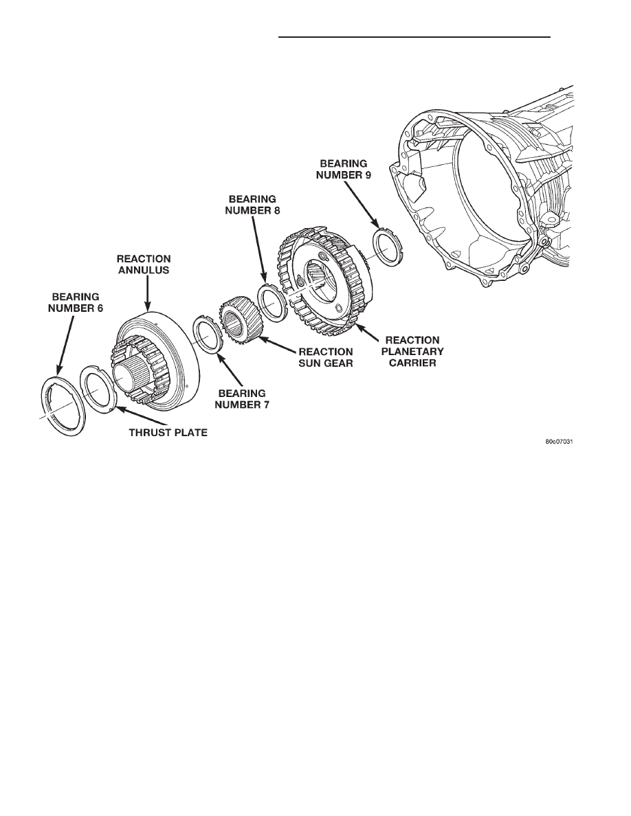
• Reaction (Fig. 25).

• Reverse (Fig. 26).

• Input (Fig. 26).

OPERATION

REACTION PLANETARY GEARTRAIN

The reaction planetary carrier and reverse sun

gear of the reaction planetary geartrain are a single
component which is held by the 2C clutch when
required. The reaction annulus gear is a stand alone
component that can be driven by the reverse clutch
or held by the 4C clutch. The reaction sun gear is
driven by the overdrive clutch.

REVERSE PLANETARY GEARTRAIN

The reverse planetary geartrain is the middle of the

three planetary sets. The reverse planetary carrier can
be driven by the overdrive clutch as required. The
reverse planetary carrier is also splined to the input
annulus gear, which can be held by the low/reverse
clutch. The reverse planetary annulus, input planetary
carrier, and output shaft are all one piece.

INPUT PLANETARY GEARTRAIN

The

input

sun

gear

of

the

input

planetary

geartrain is driven by the underdrive clutch.

GEARSHIFT MECHANISM

DESCRIPTION

The gear shift mechanism provides six shift posi-

tions which are:

• Park (P)

• Reverse (R)

• Neutral (N)

• Drive (D)

• Manual second (2)

• Manual low (1)

Fig. 25 Reaction Planetary Geartrain

21 - 198

45RFE AUTOMATIC TRANSMISSION

WJ

DESCRIPTION AND OPERATION (Continued)

OPERATION

Manual low (1) range provides first gear only.

Overrun braking is also provided in this range. Man-
ual second (2) range provides first and second gear
only.

Drive range provides first, second third and over-

drive fourth gear ranges. The shift into overdrive
fourth gear range occurs only after the transmission
has completed the shift into D third gear range. No
further movement of the shift mechanism is required
to complete the 3-4 shift.

The fourth gear upshift occurs automatically when

the overdrive selector switch is in the ON position.
An upshift to fourth gear may not occur or may be
delayed in some of the possible shift schedules. Refer
to the Transmission Control Module information for
further details.

OVERDRIVE OFF SWITCH

DESCRIPTION

The overdrive OFF (control) switch is located in

the shifter handle. The switch is a momentary con-
tact device that signals the PCM to toggle current
status of the overdrive function.

OPERATION

At key-on, overdrive operation is allowed. Pressing

the switch once causes the overdrive OFF mode to be
entered and the overdrive OFF switch lamp to be
illuminated. Pressing the switch a second time
causes normal overdrive operation to be restored and
the overdrive lamp to be turned off. The overdrive
OFF mode defaults to ON after the ignition switch is
cycled OFF and ON. The normal position for the con-
trol switch is the ON position. The switch must be in
this position to energize the solenoid and allow a 3-4
upshift. The control switch indicator light illuminates
only when the overdrive switch is turned to the OFF
position, or when illuminated by the transmission
control module.

BRAKE TRANSMISSION SHIFT INTERLOCK
MECHANISM

DESCRIPTION

The Brake Transmission Shifter/Ignition Interlock

(BTSI), is a cable and solenoid operated system. It
interconnects

the

automatic

transmission

floor

mounted shifter to the steering column ignition
switch (Fig. 27).

Fig. 26 Reverse/Input Planetary Geartrain

WJ

45RFE AUTOMATIC TRANSMISSION

21 - 199

DESCRIPTION AND OPERATION (Continued)

OPERATION

The system locks the shifter into the PARK posi-

tion. The interlock system is engaged whenever the
ignition switch is in the LOCK or ACCESSORY posi-
tion. An additional electrically activated feature will
prevent shifting out of the PARK position unless the
brake pedal is depressed at least one-half an inch. A
magnetic holding device in line with the park lock
cable is energized when the ignition is in the RUN
position. When the key is in the RUN position and
the brake pedal is depressed, the shifter is unlocked
and will move into any position. The interlock system
also prevents the ignition switch from being turned
to the LOCK or ACCESSORY position, unless the
shifter is fully locked into the PARK position.

TRANSMISSION CONTROL MODULE

DESCRIPTION

The Transmission Control Module (TCM) is located

in the engine compartment on the right (passenger)
side and is mounted to the inner fender (Fig. 28).

OPERATION

The TCM is the controlling unit for all electronic

operations of the transmission. The TCM receives
information regarding vehicle operation from both
direct and indirect inputs, and selects the operational
mode of the transmission. Direct inputs are hard-
wired to, and used specifically by the TCM. Indirect
inputs originate from other components/modules, and

Fig. 27 Ignition Interlock Cable

1 – SHIFT MECHANISM
2 – SHIFTER BTSI LEVER
3 – ADJUSTMENT CLIP

4 – STEERING COLUMN ASSEMBLY
5 – INTERLOCK CABLE

Fig. 28 Transmission Control Module Location

21 - 200

45RFE AUTOMATIC TRANSMISSION

WJ

DESCRIPTION AND OPERATION (Continued)

are shared with the TCM via the vehicle communica-
tion bus.

Some examples of direct inputs to the TCM are:
• Battery (B+) voltage

• Ignition “ON” voltage

• Transmission Control Relay (Switched B+)

• Throttle Position Sensor

• Crankshaft Position Sensor

• Transmission Range Sensor

• Pressure Switches

• Transmission Temperature Sensor

• Input Shaft Speed Sensor

• Output Shaft Speed Sensor

• Line Pressure Sensor
Some examples of indirect inputs to the TCM

are:

• Engine/Body Identification

• Manifold Pressure

• Target Idle

• Torque Reduction Confirmation

• Engine Coolant Temperature

• Ambient/Battery Temperature

• DRB Scan Tool Communication
Based on the information received from these var-

ious inputs, the TCM determines the appropriate
shift schedule and shift points, depending on the
present operating conditions and driver demand.
This is possible through the control of various direct
and indirect outputs.

Some examples of TCM direct outputs are:
• Transmission Control Relay

• Solenoids

• Torque Reduction Request
Some examples of TCM indirect outputs are:
• Transmission Temperature (to PCM)

• PRNDL Position (to BCM)
In addition to monitoring inputs and controlling

outputs, the TCM has other important responsibili-
ties and functions:

• Storing and maintaining Clutch Volume Indexes

(CVI)

• Storing and selecting appropriate Shift Sched-

ules

• System self-diagnostics

• Diagnostic capabilities (with DRB scan tool)

NOTE: If the TCM has been replaced, the “Quick
Learn Procedure” must be performed. Refer to
“Quick Learn Procedure” in Service Procedures of
this group.

CLUTCH VOLUME INDEXES

An important function of the TCM is to monitor

Clutch Volume Indexes (CVI). CVIs represent the vol-
ume of fluid needed to compress a clutch pack.

The TCM monitors gear ratio changes by monitor-

ing the Input and Output Speed Sensors. The Input,
or Turbine Speed Sensor sends an electrical signal to
the TCM that represents input shaft rpm. The Out-
put Speed Sensor provides the TCM with output
shaft speed information.

By comparing the two inputs, the TCM can deter-

mine transmission gear position. This is important to
the CVI calculation because the TCM determines
CVIs by monitoring how long it takes for a gear
change to occur (Fig. 29).

Gear ratios can be determined by using the DRB

Scan Tool and reading the Input/Output Speed Sen-
sor values in the “Monitors” display. Gear ratio can
be obtained by dividing the Input Speed Sensor value
by the Output Speed Sensor value.

For example, if the input shaft is rotating at 1000

rpm and the output shaft is rotating at 500 rpm,
then the TCM can determine that the gear ratio is
2:1. In direct drive (3rd gear), the gear ratio changes
to 1:1. The gear ratio changes as clutches are applied
and released. By monitoring the length of time it
takes for the gear ratio to change following a shift
request, the TCM can determine the volume of fluid
used to apply or release a friction element.

Fig. 29 Example of CVI Calculation

1 – OUTPUT SPEED SENSOR
2 – OUTPUT SHAFT
3 – CLUTCH PACK
4 – SEPARATOR PLATE
5 – FRICTION DISCS
6 – INPUT SHAFT
7 – INPUT SPEED SENSOR
8 – PISTON AND SEAL

WJ

45RFE AUTOMATIC TRANSMISSION

21 - 201

DESCRIPTION AND OPERATION (Continued)


Content   ..  452  453  454  455   ..