Jeep Grand Cherokee WJ. Manual - part 426


  Index      Jeep     Jeep Grand Cherokee WJ - service repair manual 2001 year


Search            


Content   ..  424  425  426  427   ..


Jeep Grand Cherokee WJ. Manual - part 426


(2) Check condition of manual lever shaft seal in

transmission case. Replace seal if lip is cut or worn.
Install new seal with 15/16 deep well socket (Fig.
100).

(3) Check condition of seals on accumulator piston

(Fig. 101). Install new piston seals, if necessary.

(4) Place valve body manual lever in low (1 posi-

tion) so ball on park lock rod will be easier to install
in sprag.

(5) Lubricate shaft of manual lever with petroleum

jelly. This will ease inserting shaft through seal in
case.

(6) Lubricate seal rings on valve body harness con-

nector with petroleum jelly.

(7) Position valve body in case and work end of

park lock rod into and through pawl sprag. Turn pro-
peller shaft to align sprag and park lock teeth if nec-
essary. The rod will click as it enters pawl. Move rod
to check engagement.

CAUTION: It is possible for the park rod to displace
into a cavity just above the pawl sprag during
installation. Make sure the rod is actually engaged
in the pawl and has not displaced into this cavity.

(8) Install accumulator springs and piston into

case. Then swing valve body over piston and outer
spring to hold it in place.

(9) Align accumulator piston and outer spring,

manual lever shaft and electrical connector in case.

(10) Then seat valve body in case and install one

or two bolts to hold valve body in place.

(11) Tighten valve body bolts alternately and

evenly to 11 N·m (100 in. lbs.) torque.

(12) Install new fluid filter on valve body. Tighten

filter screws to 4 N·m (35 in. lbs.) torque.

(13) Install throttle and gearshift levers on valve

body manual lever shaft.

(14) Check and adjust front and rear bands if nec-

essary.

(15) Connect solenoid case connector wires.
(16) Install oil pan and new gasket. Tighten pan

bolts to 17 N·m (13 ft. lbs.) torque.

(17) Lower vehicle and fill transmission with

Mopar

t ATF Plus 3, type 7176 fluid.

(18) Check and adjust gearshift and throttle valve

cables, if necessary.

OVERDRIVE UNIT

REMOVAL

(1) Shift transmission into Park.
(2) Raise vehicle.
(3) Remove transfer case, if equipped.
(4) Mark propeller shaft universal joint(s) and axle

pinion yoke, or the companion flange and flange

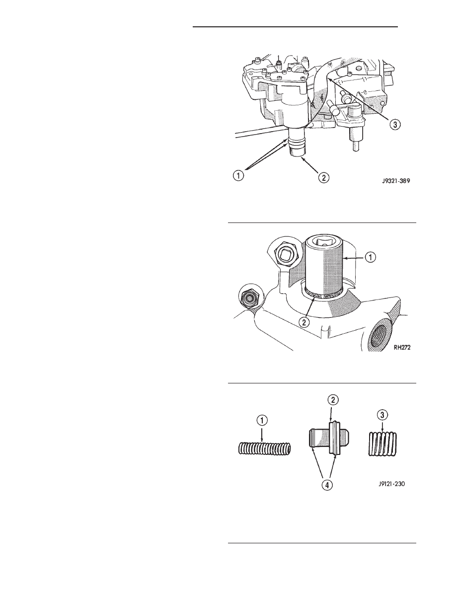
Fig. 99 Valve Body Harness Connector O-Ring Seal

1 – CONNECTOR O-RINGS
2 – VALVE BODY HARNESS CONNECTOR
3 – HARNESS

Fig. 100 Manual Lever Shaft Seal

1 – 15/16” SOCKET
2 – SEAL

Fig. 101 Accumulator Piston Components

1 – INNER SPRING
2 – ACCUMULATOR PISTON
3 – OUTER SPRING
4 – SEAL RINGS

21 - 86

42RE AUTOMATIC TRANSMISSION

WJ

REMOVAL AND INSTALLATION (Continued)

yoke, for alignment reference at installation, if necc-
esary.

(5) Disconnect and remove the rear propeller shaft,

if necessary.

(6) Remove transmission oil pan, remove gasket,

drain oil and reinstall pan.

(7) If overdrive unit had malfunctioned, or if fluid

is contaminated, remove entire transmission. If diag-
nosis indicated overdrive problems only, remove just
the overdrive unit.

(8) Support transmission with transmission jack.
(9) Remove vehicle speed sensor.
(10) Remove bolts attaching overdrive unit to

transmission (Fig. 102).

CAUTION: Support the overdrive unit with a jack
before moving it rearward. This is necessary to pre-
vent damaging the intermediate shaft. Do not allow
the shaft to support the entire weight of the over-
drive unit.

(11) Carefully work overdrive unit off intermediate

shaft. Do not tilt unit during removal. Keep it as
level as possible.

(12) If overdrive unit does not require service,

immediately insert Alignment Tool 6227-2 in splines
of planetary gear and overrunning clutch to prevent
splines from rotating out of alignment. If misalign-
ment occurs, overdrive unit will have to be disassem-
bled in order to realign splines.

(13) Remove and retain overdrive piston thrust

bearing. Bearing may remain on piston or in clutch
hub during removal.

(14) Position drain pan on workbench.
(15) Place overdrive unit over drain pan. Tilt unit

to drain residual fluid from case.

(16) Examine fluid for clutch material or metal

fragments. If fluid contains these items, overhaul will
be necessary.

(17) If overdrive unit does not require any service,

leave alignment tool in position. Tool will prevent
accidental misalignment of planetary gear and over-
running clutch splines.

INSTALLATION

(1) Be sure overdrive unit Alignment Tool 6227-2

is fully seated before moving unit. If tool is not
seated and gear splines rotate out of alignment, over-
drive unit will have to be disassembled in order to
realign splines.

(2) If overdrive piston retainer was not removed

during service and original case gasket is no longer
reusable, prepare new gasket by trimming it.

(3) Cut out old case gasket around piston retainer

with razor knife (Fig. 103).

(4) Use old gasket as template and trim new gas-

ket to fit.

(5) Position new gasket over piston retainer and

on transmission case. Use petroleum jelly to hold
gasket in place if necessary. Do not use any type of
sealer to secure gasket. Use petroleum jelly only.

(6) Install selective spacer on intermediate shaft, if

removed. Spacer goes in groove just rearward of
shaft rear splines (Fig. 104).

(7) Install thrust bearing in overdrive unit sliding

hub. Use petroleum jelly to hold bearing in position.

CAUTION: Be sure the shoulder on the inside diam-
eter of the bearing is facing forward.

Fig. 102 Overdrive Unit Bolts

1 – OVERDRIVE UNIT
2 – ATTACHING BOLTS (7)

Fig. 103 Trimming Overdrive Case Gasket

1 – GASKET
2 – SHARP KNIFE

WJ

42RE AUTOMATIC TRANSMISSION

21 - 87

REMOVAL AND INSTALLATION (Continued)

(8) Verify that splines in overdrive planetary gear

and overrunning clutch hub are aligned with Align-
ment Tool 6227-2. Overdrive unit cannot be installed
if splines are not aligned. If splines have rotated out
of alignment, unit will have to be disassembled to
realign splines.

(9) Carefully slide Alignment Tool 6227-2 out of

overdrive planetary gear and overrunning clutch
splines.

(10) Raise overdrive unit and carefully slide it

straight onto intermediate shaft. Insert park rod into
park lock reaction plug at same time. Avoid tilting
overdrive during installation as this could cause
planetary gear and overrunning clutch splines to
rotate out of alignment. If this occurs, it will be nec-
essary to remove and disassemble overdrive unit to
realign splines.

(11) Work overdrive unit forward on intermediate

shaft until seated against transmission case.

(12) Install bolts attaching overdrive unit to trans-

mission unit. Tighten bolts in diagonal pattern to 34
N·m (25 ft. lbs).

(13) Install speed sensor.
(14) Connect speed sensor and overdrive wires.
(15) Install the transfer case, if equipped.
(16) Align and install rear propeller shaft, if nec-

essary.

OVERDRIVE HOUSING BUSHING

REMOVAL

(1) Remove overdrive housing yoke seal.
(2) Insert Remover 6957 into overdrive housing.

Tighten tool to bushing and remove bushing (Fig.
105).

INSTALLATION

(1) Align bushing oil hole with oil slot in overdrive

housing.

(2) Tap bushing into place with Installer 6951 and

Handle C-4171.

(3) Install new oil seal in housing using Seal

Installer C-3995–A (Fig. 106).

OUTPUT SHAFT REAR BEARING

REMOVAL

(1) Remove overdrive unit from the vehicle.
(2) Remove overdrive geartrain from housing.
(3) Remove snap ring holding output shaft rear

bearing into overdrive housing (Fig. 107).

(4) Using a suitable driver inserted through the

rear end of housing, drive bearing from housing.

INSTALLATION

(1) Place replacement bearing in position in hous-

ing.

(2) Using a suitable driver, drive bearing into

housing until the snap ring groove is visible.

(3) Install snap ring to hold bearing into housing

(Fig. 107).

Fig. 104 Intermediate Shaft Selective Spacer

Location

1 – SELECTIVE SPACER
2 – SPACER GROOVE
3 – INTERMEDIATE SHAFT

Fig. 105 Bushing Removal—Typical

1 – REMOVER 6957
2 – EXTENSION HOUSING BUSHING

Fig. 106 Overdrive Housing Seal Installation

1 – SPECIAL TOOL C-3995–A OR C-3972–A
2 – SPECIAL TOOL C-4471

21 - 88

42RE AUTOMATIC TRANSMISSION

WJ

REMOVAL AND INSTALLATION (Continued)

(4) Install overdrive geartrain into housing.
(5) Install overdrive unit in vehicle.

OUTPUT SHAFT FRONT BEARING

REMOVAL

(1) Remove overdrive unit from the vehicle.
(2) Remove overdrive geartrain from housing.
(3) Remove snap ring holding output shaft front

bearing to overdrive geartrain. (Fig. 108).

(4) Pull bearing from output shaft.

INSTALLATION

(1) Place

replacement

bearing

in

position

on

geartrain with locating retainer groove toward the
rear.

(2) Push bearing onto shaft until the snap ring

groove is visible.

(3) Install snap ring to hold bearing onto output

shaft (Fig. 108).

(4) Install overdrive geartrain into housing.
(5) Install overdrive unit in vehicle.

DISASSEMBLY AND ASSEMBLY

VALVE BODY

Remove the valve body from the transmission,

refer to Removal and Installation procedures section
in this group.

DISASSEMBLY

CAUTION: Do not clamp any valve body compo-
nent in a vise. This practice can damage the com-
ponent resulting in unsatisfactory operation after

assembly and installation. Do not use pliers to
remove any of the valves, plugs or springs and do
not force any of the components out or into place.
The valves and valve body housings will be dam-
aged if force is used. Tag or mark the valve body
springs for reference as they are removed. Do not
allow them to become intermixed.

(1) Remove fluid filter.
(2) Disconnect wires from governor pressure sen-

sor and solenoid.

(3) Remove screws attaching governor body and

retainer plate to transfer plate.

(4) Remove retainer plate, governor body and gas-

ket from transfer plate.

(5) Remove governor pressure sensor from gover-

nor body

(6) Remove governor pressure solenoid by pulling

it straight out of bore in governor body. Remove and
discard solenoid O-rings if worn, cut, or torn.

(7) Remove small shoulder bolt that secures sole-

noid harness case connector to 3-4 accumulator hous-
ing (Fig. 109). Retain shoulder bolt. Either tape
it to harness or thread it back into accumulator
housing after connector removal.

(8) Unhook overdrive/converter solenoid harness

from 3-4 accumulator cover plate (Fig. 110).

(9) Turn valve body over and remove screws that

attach overdrive/converter solenoid assembly to valve
body (Fig. 111).

(10) Remove solenoid and harness assembly from

valve body (Fig. 112).

(11) Remove boost valve cover (Fig. 113).
(12) Remove boost valve retainer, valve spring and

boost valve (Fig. 114).

Fig. 107 Output Shaft Rear Bearing

1 – OUTPUT SHAFT REAR BEARING
2 – OVERDRIVE HOUSING
3 – SNAP RING

Fig. 108 Output Shaft Front Bearing

1 – OUTPUT SHAFT FRONT BEARING
2 – SNAP RING
3 – OUTPUT SHAFT
4 – GROOVE TO REAR
5 – OVERDRIVE GEARTRAIN

WJ

42RE AUTOMATIC TRANSMISSION

21 - 89

REMOVAL AND INSTALLATION (Continued)


Content   ..  424  425  426  427   ..