Jeep Grand Cherokee WJ. Manual - part 424


  Index      Jeep     Jeep Grand Cherokee WJ - service repair manual 2001 year


Search            


Content   ..  422  423  424  425   ..


Jeep Grand Cherokee WJ. Manual - part 424


INSTALLATION

(1) Check torque converter hub and hub drive

notches for sharp edges burrs, scratches, or nicks.
Polish the hub and notches with 320/400 grit paper
and crocus cloth if necessary. The hub must be
smooth to avoid damaging pump seal at installation.

(2) Lubricate oil pump seal lip with transmission

fluid.

(3) Align converter and oil pump.
(4) Carefully insert converter in oil pump. Then

rotate converter back and forth until fully seated in
pump gears.

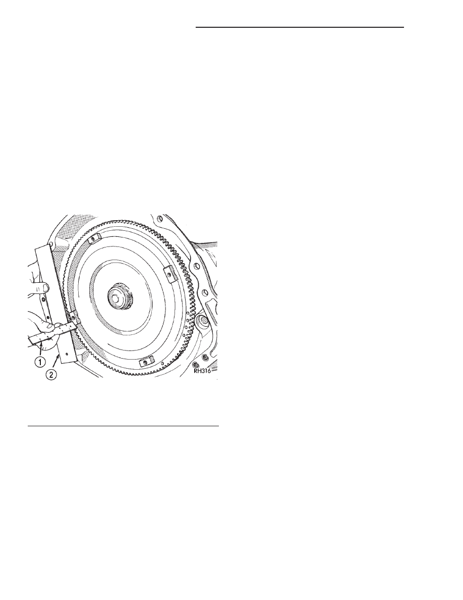
(5) Check converter seating with steel scale and

straightedge (Fig. 82). Surface of converter lugs
should be 1/2 in. to rear of straightedge when con-
verter is fully seated.

(6) Temporarily secure converter with C-clamp.

(7) Position transmission on jack and secure it

with chains.

(8) Check

condition

of

converter

driveplate.

Replace the plate if cracked, distorted or damaged.
Also be sure transmission dowel pins are seated
in engine block and protrude far enough to
hold transmission in alignment.

(9) Apply a light coating of Mopar

t High Temp

grease to the torque converter hub pocket in the rear
of the crankshaft.

(10) Raise transmission and align converter with

drive plate and converter housing with engine block.

(11) Move transmission forward. Then raise, lower

or tilt transmission to align converter housing with
engine block dowels.

(12) Carefully work transmission forward and over

engine block dowels until converter hub is seated in
crankshaft.

(13) Install two bolts to attach converter housing

to engine.

(14) Install the upper transmission bending braces

to the torque converter housing and the overdrive
unit. Tighten the bolts to 41 N·m (30 ft. lbs.).

(15) Install remaining torque converter housing to

engine bolts. Tighten to 68 N·m (50 ft. lbs.).

(16) Install

rear

transmission

crossmember.

Tighten crossmember to frame bolts to 68 N·m (50 ft.
lbs.).

(17) Install rear support to transmission. Tighten

bolts to 47 N·m (35 ft. lbs.).

(18) Lower transmission onto crossmember and

install bolts attaching transmission mount to cross-
member. Tighten clevis bracket to crossmember bolts
to 47 N·m (35 ft. lbs.). Tighten the clevis bracket to
rear support bolt to 68 N·m (50 ft. lbs.).

(19) Remove engine support fixture.
(20) Install crankshaft position sensor.
(21) Install new plastic retainer grommet on any

shift cable that was disconnected. Grommets should
not be reused. Use pry tool to remove rod from grom-
met and cut away old grommet. Use pliers to snap
new grommet into cable and to snap grommet onto
lever.

(22) Connect gearshift and throttle valve cable to

transmission.

(23) Connect wires to park/neutral position switch

and transmission solenoid connector. Be sure trans-
mission harnesses are properly routed.

CAUTION: It is essential that correct length bolts
be used to attach the converter to the driveplate.
Bolts that are too long will damage the clutch sur-
face inside the converter.

(24) Install torque converter-to-driveplate bolts.

Tighten bolts to 31 N·m (270 in. lbs.).

(25) Install converter housing access cover. Tighten

bolt to 23 N·m (200 in. lbs.).

(26) Install the bell housing brace to the torque

converter cover and the engine to transmission bend-
ing brace. Tighten the bolts and nut to 41 N·m (30 ft.
lbs.).

(27) Install starter motor and cooler line bracket.
(28) Connect cooler lines to transmission.
(29) Install transmission fill tube. Install new seal

on tube before installation.

(30) Install exhaust components.
(31) Install transfer case. Tighten transfer case

nuts to 35 N·m (26 ft. lbs.).

Fig. 82 Typical Method Of Checking Converter

Seating

1 – SCALE
2 – STRAIGHTEDGE

21 - 78

42RE AUTOMATIC TRANSMISSION

WJ

REMOVAL AND INSTALLATION (Continued)

(32) Install the transfer case shift cable to the

cable support bracket and the transfer case shift
lever.

(33) Align and connect propeller shaft(s).
(34) Adjust gearshift linkage and throttle valve

cable if necessary.

(35) Lower vehicle.
(36) Fill transmission with Mopar

t ATF Plus 3,

Type 7176 fluid.

TORQUE CONVERTER

REMOVAL

(1) Remove transmission and torque converter

from vehicle.

(2) Place a suitable drain pan under the converter

housing end of the transmission.

CAUTION: Verify that transmission is secure on the
lifting device or work surface, the center of gravity
of the transmission will shift when the torque con-
verter is removed creating an unstable condition.

The torque converter is a heavy unit. Use caution

when separating the torque converter from the
transmission.

(3) Pull the torque converter forward until the cen-

ter hub clears the oil pump seal.

(4) Separate the torque converter from the trans-

mission.

INSTALLATION

Check converter hub and drive notches for sharp

edges, burrs, scratches, or nicks. Polish the hub and
notches with 320/400 grit paper or crocus cloth if nec-
essary. The hub must be smooth to avoid damaging
the pump seal at installation. Check that the torque
converter hub o-ring on the 45RFE torque converter
hub is not damaged. Replace if necessary.

(1) Lubricate oil pump seal lip with transmission

fluid.

(2) Place torque converter in position on transmis-

sion.

CAUTION: Do not damage oil pump seal or bushing
while inserting torque converter into the front of the
transmission.

(3) Align torque converter to oil pump seal open-

ing.

(4) Insert torque converter hub into oil pump.
(5) While pushing torque converter inward, rotate

converter until converter is fully seated in the oil
pump gears.

(6) Check converter seating with a scale and

straightedge (Fig. 83). Surface of converter lugs

should be 1/2 in. to rear of straightedge when con-
verter is fully seated.

(7) If necessary, temporarily secure converter with

C-clamp attached to the converter housing.

(8) Install the transmission in the vehicle.
(9) Fill the transmission with the recommended

fluid.

PARK/NEUTRAL POSITION SWITCH

REMOVAL

(1) Raise vehicle and position drain pan under

switch.

(2) Disconnect switch wires.
(3) Remove switch from case.

INSTALLATION

(1) Move shift lever to Park and Neutral positions.

Verify that switch operating lever fingers are cen-
tered in switch opening in case (Fig. 84).

(2) Install new seal on switch and install switch in

case. Tighten switch to 34 N·m (25 ft. lbs.) torque.

(3) Test continuity of new switch with 12V test

lamp.

(4) Connect switch wires and lower vehicle.
(5) Top off transmission fluid level.

GEARSHIFT CABLE

REMOVAL

(1) Shift transmission into Park.
(2) Raise vehicle.

Fig. 83 Checking Torque Converter Seating–Typical

1 – SCALE
2 – STRAIGHTEDGE

WJ

42RE AUTOMATIC TRANSMISSION

21 - 79

REMOVAL AND INSTALLATION (Continued)

(3) Remove the shift cable eyelet from the trans-

mission manual shift lever (Fig. 85).

(4) Remove shift cable from the cable support

bracket.

(5) Lower vehicle.
(6) Remove shift lever bezel and necessary console

parts for access to shift lever assembly and shift
cable.

(7) Disconnect cable at shift lever and shifter

assembly bracket (Fig. 86).

(8) Remove the nuts holding the shift cable seal

plate to the floor pan (Fig. 87).

(9) Pull cable through floor panel opening.
(10) Remove shift cable from vehicle.

INSTALLATION

(1) Route cable through hole in floor pan.
(2) Install seal plate to studs in floor pan.
(3) Install nuts to hold seal plate to floor pan.

Tighten nuts to 7 N·m (65 in. lbs.).

(4) Install the shift cable to the shifter assembly

bracket. Push cable into the bracket until secure.

(5) Place the floor shifter lever in park position.
(6) Loosen the adjustment screw on the shift cable.
(7) Snap the shift cable onto the shift lever pin.
(8) Raise the vehicle.
(9) Install the shift cable to the shift cable support

bracket.

Fig. 84 Park/Neutral Position Switch

1 – NEUTRAL CONTACT
2 – MANUAL LEVER AND SWITCH PLUNGER IN REVERSE

POSITION

3 – PARK CONTACT
4 – SWITCH

Fig. 85 Remove Shift Cable From Transmission

Fig. 86 Transmission Shift Cable at Shifter

1 – SHIFT LEVER PIN
2 – ADJUSTMENT SCREW
3 – SHIFT CABLE
4 – SHIFTER ASSEMBLY BRACKET

Fig. 87 Shift Cables at Floor Pan

1 – SEAL PLATES
2 – TRANSMISSION SHIFT CABLE
3 – TRANSFER CASE SHIFT CABLE

21 - 80

42RE AUTOMATIC TRANSMISSION

WJ

REMOVAL AND INSTALLATION (Continued)

(10) Shift the transmission into PARK. PARK is

the rearmost detent position on the transmission
manual shift lever.

(11) Snap the shift cable onto the transmission

manual shift lever.

(12) Lower vehicle.
(13) Verify that the shift lever is in the PARK posi-

tion.

(14) Tighten the adjustment screw to 7 N·m (65 in.

lbs.).

(15) Verify correct shifter operation.
(16) Install shift lever bezel and any console parts

removed for access to shift lever assembly and shift
cable.

SHIFTER

REMOVAL

(1) Shift transmission into Park.
(2) Remove shift lever bezel and any necessary

console parts for access to shift lever assembly and
shifter cables.

(3) Disconnect the transmission shift cable at shift

lever and shifter assembly bracket (Fig. 88).

(4) Disconnect the brake transmission interlock

cable from the shifter BTSI lever and the shifter
assembly bracket.

(5) Disconnect the transfer case shift cable from

the transfer case shift lever pin (Fig. 90).

(6) Remove the clip holding the transfer case shift

cable to the shifter assembly bracket.

(7) Remove the transfer case shift cable from the

shifter assembly bracket.

(8) Disengage

all

wiring

connectors

from

the

shifter assembly.

(9) Remove all nuts holding the shifter assembly to

the floor pan (Fig. 91).

(10) Remove the shifter assembly from the vehicle.

INSTALLATION

(1) Install shifter assembly onto the shifter assem-

bly studs on the floor pan.

(2) Install the nuts to hold the shifter assembly

onto the floor pan. Tighten nuts to 28 N·m (250 in.
lbs.).

(3) Install wiring harness to the shifter assembly

bracket. Engage any wire connectors removed from
the shifter assembly.

(4) Install the transfer case shift cable to the

shifter assembly bracket. Install clip to hold cable to
the bracket.

(5) Snap the transfer case shift cable onto the

transfer case shift lever pin.

(6) Install the brake transmission interlock cable

into the shifter assembly bracket and into the shifter
BTSI lever.

(7) Install the shift cable to the shifter assembly

bracket. Push cable into the bracket until secure.

(8) Place the floor shifter lever in park position.
(9) Loosen the adjustment screw on the shift cable.
(10) Snap the shift cable onto the shift lever pin.
(11) Verify that the shift lever is in the PARK posi-

tion.

(12) Tighten the adjustment screw to 7 N·m (65 in.

lbs.).

(13) Verify correct shifter operation.
(14) Install shift lever bezel and any console parts

removed for access to shift lever assembly and shift
cables.

Fig. 88 Transmission Shift Cable at Shifter

1 – SHIFT LEVER PIN
2 – ADJUSTMENT SCREW
3 – SHIFT CABLE
4 – SHIFTER ASSEMBLY BRACKET

WJ

42RE AUTOMATIC TRANSMISSION

21 - 81

REMOVAL AND INSTALLATION (Continued)


Content   ..  422  423  424  425   ..