Jeep Grand Cherokee WJ. Manual - part 403


  Index      Jeep     Jeep Grand Cherokee WJ - service repair manual 2001 year


Search            


Content   ..  401  402  403  404   ..


Jeep Grand Cherokee WJ. Manual - part 403


(13) Install the cluster bezel by pulling it from the

instrument panel (Fig. 4).

(14) Align the steering wheel with the column

index spline and install the wheel on the column
shaft. Pull the clockspring wire harness through the
steering wheel armature spokes.

(15) Install and tighten the steering wheel mount-

ing nut to 61 N·m (45 ft. lbs.).

(16) Connect the steering wheel wire harness con-

nector to the clock spring connector.

(17) Install

the

airbag,

refer

to

Group

8M

Restraint Systems for service procedures.

(18) Connect the negative (ground) cable to the

battery.

SPECIFICATIONS

TORQUE CHART

DESCRIPTION

TORQUE

Steering Column

Steering Wheel Nut . . . . . . . . 61 N·m (45 ft. lbs.)
Column Bracket Nuts . . . . . 12 N·m (105 in. lbs.)
Shaft Coupler Bolts . . . . . . . . 49 N·m (36 ft. lbs.)

SPECIAL TOOLS

STEERING COLUMN

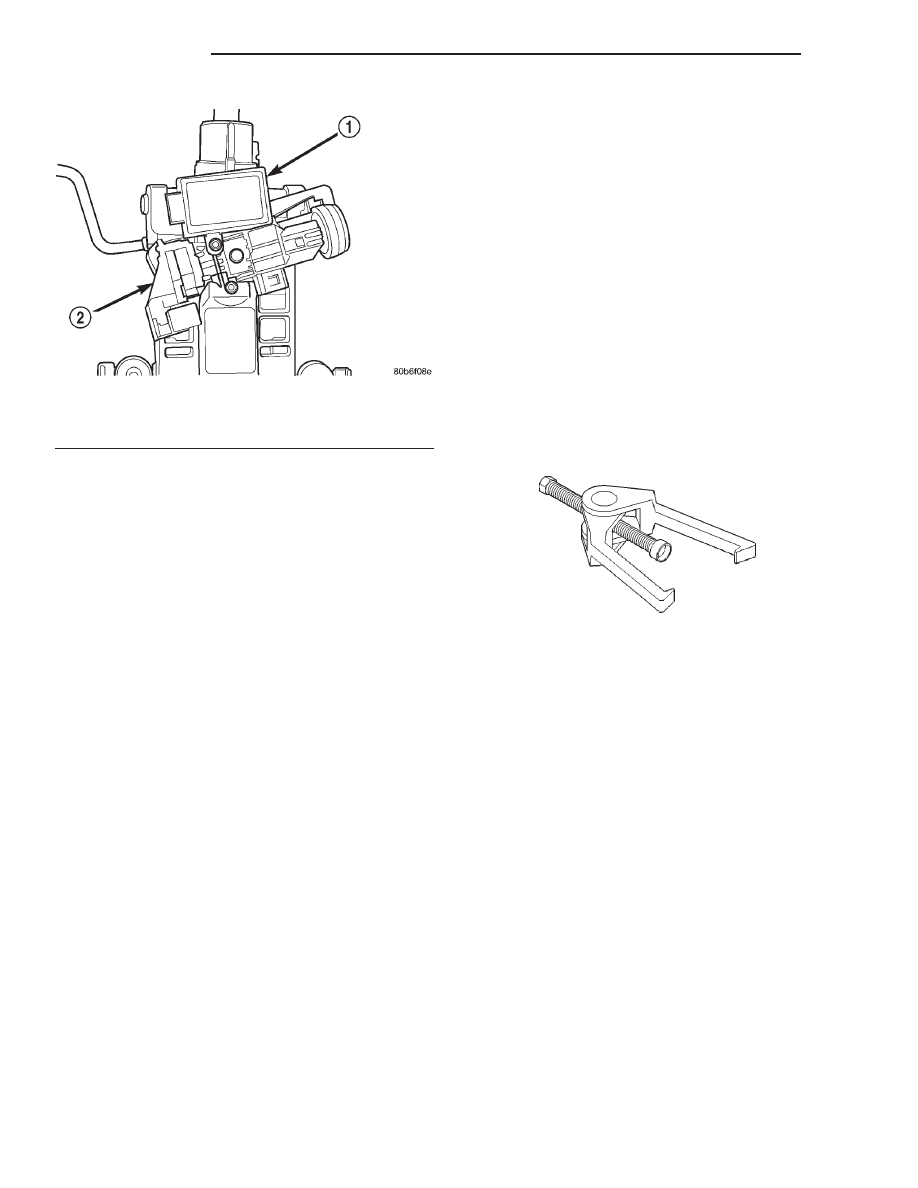
Fig. 14 Ignition Switch And SKIM

1 – SKIM
2 – IGNITION SWITCH

Puller C-3894-A

19 - 30

STEERING

WJ

REMOVAL AND INSTALLATION (Continued)

STEERING

TABLE OF CONTENTS

page

page

POWER STEERING SYSTEM – 3.1L VM

DIESEL . . . . . . . . . . . . . . . . . . . . . . . . . . . . . . . . . 1

POWER STEERING PUMP – 3.1L VM DIESEL . . . 2

POWER STEERING SYSTEM – 3.1L VM DIESEL

TABLE OF CONTENTS

page

DESCRIPTION AND OPERATION

POWER STEERING PUMP . . . . . . . . . . . . . . . . . . 1

DESCRIPTION AND OPERATION

POWER STEERING PUMP

The power steering pump used with the 3.1L VM

Diesel engine operates the same way as the power

steering pump used with the 4.0/4.7L gasoline
engines. Refer to the Description and Operation sec-
tion for the 4.0/4.7L gasoline engine power steering
pump for more information.

WJ

STEERING

19 - 1

2000 JEEP GRAND CHEROKEE

POWER STEERING PUMP – 3.1L VM DIESEL

TABLE OF CONTENTS

page

page

DESCRIPTION AND OPERATION

STEERING LINKAGE – RIGHT HAND DRIVE

VEHICLES . . . . . . . . . . . . . . . . . . . . . . . . . . . . . 2

SERVICE PROCEDURES

POWER STEERING PUMP - INITIAL

OPERATION . . . . . . . . . . . . . . . . . . . . . . . . . . . . 3

REMOVAL AND INSTALLATION

POWER STEERING PUMP - 3.1l DIESEL. . . . . . . . 3
POWER STEERING PUMP PULLEY . . . . . . . . . . . 4

SPECIFICATIONS

TORQUE CHART . . . . . . . . . . . . . . . . . . . . . . . . . . 6

DESCRIPTION AND OPERATION

STEERING LINKAGE – RIGHT HAND DRIVE
VEHICLES

Vehicles equipped with right hand drive (RHD)

steering utilize the same components of left hand
drive vehicles. RHD Steering linkage (Fig. 1) is

designed as a mirror image of left hand drive linkage
with the exception of the steering damper, which is
mounted on the same side of the vehicle weather
RHD or LHD. See figure below for reference. All
specifications are the same as LHD. Refer to Group
19, Steering of the gasoline engine service manual for
additional information.

Fig. 1 Right Hand Drive Steering Linkage

1 – PITMAN ARM
2 – STEERING DAMPENER

19 - 2

STEERING

WJ

2000 JEEP GRAND CHEROKEE

SERVICE PROCEDURES

POWER STEERING PUMP - INITIAL
OPERATION

WARNING: THE

FLUID

LEVEL

SHOULD

BE

CHECKED WITH ENGINE OFF TO PREVENT INJURY
FROM MOVING COMPONENTS.

CAUTION: Use MOPAR Power Steering Fluid or
equivalent. Do not use automatic transmission fluid
and do not overfill.

Wipe filler cap clean, then check the fluid level.

The dipstick should indicate COLD when the fluid is
at normal ambient temperature.

(1) Fill the pump fluid reservoir to the proper level

and let the fluid settle for at least two minutes.

(2) Start the engine and let run for a few seconds

then turn engine off.

(3) Add fluid if necessary. Repeat the above proce-

dure until the fluid level remains constant after run-
ning the engine.

(4) Raise the front wheels off the ground.
(5) Slowly turn the steering wheel right and left,

lightly contacting the wheel stops at least 20 times.

(6) Check the fluid level add if necessary.
(7) Lower the vehicle, start the engine and turn

the steering wheel slowly from lock to lock.

(8) Stop the engine and check the fluid level and

refill as required.

(9) If the fluid is extremely foamy or milky look-

ing, allow the vehicle to stand a few minutes and
repeat the procedure.

CAUTION: Do not run a vehicle with foamy fluid for
an extended period. This may cause pump damage.

REMOVAL AND INSTALLATION

POWER STEERING PUMP - 3.1l DIESEL

REMOVAL

(1) Open the hood and disconnect the negative bat-

tery cable.

(2) Remove the intercooler outlet hose from the

vehicle (Fig. 2).

(3) Remove the accessory drive belt from the power

steering pump pulley (Fig. 3). Refer to Group 7, Cool-
ing System for the procedure.

(4) Install a allen wrench in the power steering

pump center shaft to hold the pump in position.
Remove the (3) power steering pump pulley retaining
bolts (Fig. 4).

Fig. 2 Diesel Engine Compartment

1 – INTERCOOLER INLET HOSE
2 – COOLANT RECOVERY HOSE
3 – REFRIGERANT LINE SUPPORT BRACKET
4 – INTERCOOLER OUTLET HOSE
5 – FAN SHROUD

Fig. 3 Removing Accessory Drive Belt

1 – FAN SHROUD
2 – 1/2 DRIVE BAR
3 – AUTOMATIC BELT TENSIONER

WJ

STEERING

19 - 3

2000 JEEP GRAND CHEROKEE


Content   ..  401  402  403  404   ..