Jeep Grand Cherokee WJ. Manual - part 400


  Index      Jeep     Jeep Grand Cherokee WJ - service repair manual 2001 year


Search            


Content   ..  398  399  400  401   ..


Jeep Grand Cherokee WJ. Manual - part 400


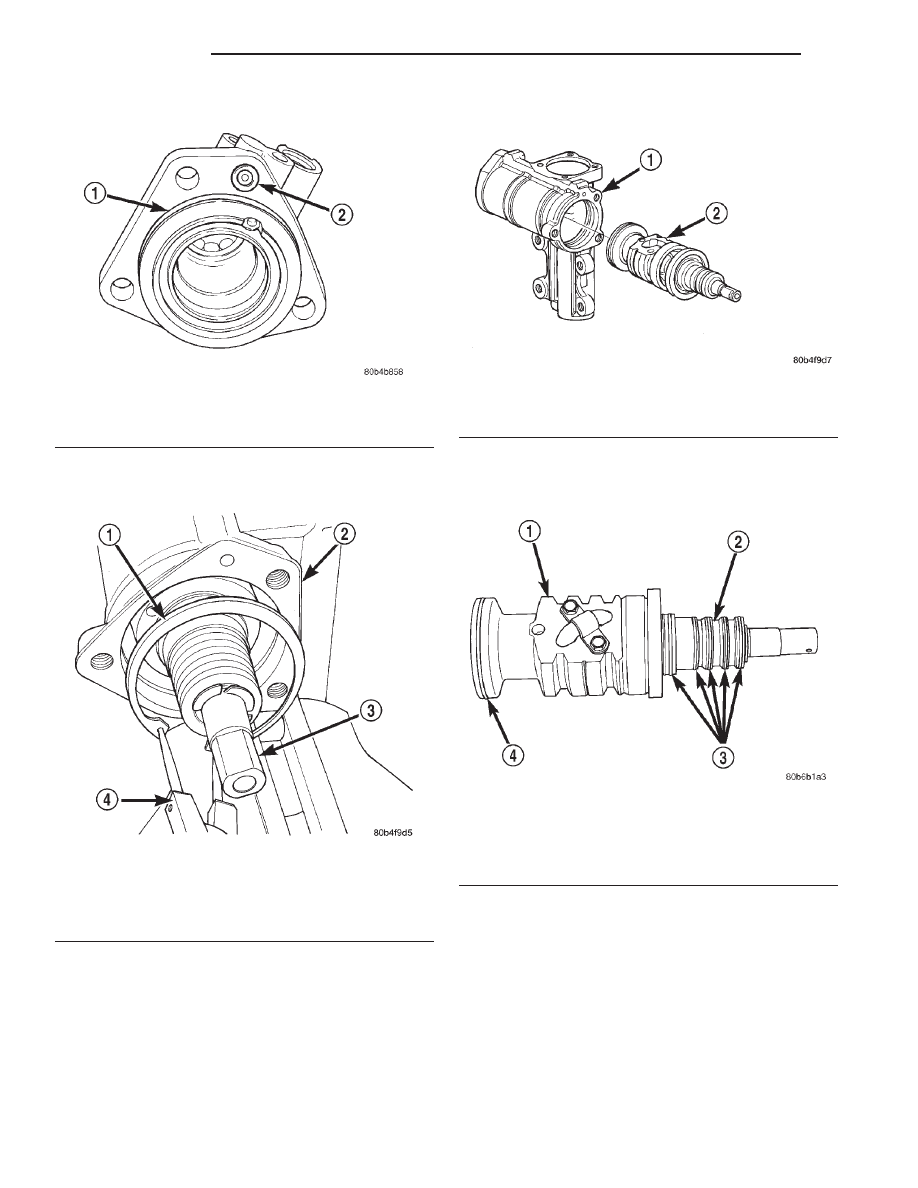
(8) Remove stub shaft housing o-rings (Fig. 20).

(9) Remove the rack piston/valve assembly retain-

ing ring with snap ring pliers (Fig. 21).

(10) Pull the rack piston/valve assembly out of the

gear housing (Fig. 22).

NOTE: If the rack piston is damage the gear assem-
bly must be replaced.

(11) Remove teflon rings and o-ring (Fig. 23) from

the rack piston/valve assembly.

CAUTION: The rack piston teflon ring and o-ring
must

be

replaced

whenever

the

assembly

is

removed from the housing.

(12) Remove pitman shaft dust seal from the hous-

ing with Puller 7794-A and Slide Hammer C-637
(Fig. 24).

(13) Remove pitman shaft oil seal retaining ring

from the housing with snap ring pliers (Fig. 25).

(14) Remove metal backup washer then plastic

backup washer from the housing (Fig. 26).

(15) Remove oil seal from the housing with a

Puller 7794-A and Slide Hammer C-637 (Fig. 27).

Fig. 20 O-Rings

1 – O-RING
2 – O-RING

Fig. 21 Retaining Ring

1 – RETAINING RING
2 – GEAR HOUSING
3 – STUB SHAFT
4 – SNAP RING PLIERS

Fig. 22 Rack Piston/Valve Assembly

1 – GEAR HOUSING
2 – RACK PISTON VALVE ASSEMBLY

Fig. 23 Teflon Rings And O-Ring

1 – RACK PISTON
2 – VALVE
3 – TEFLON RINGS
4 – TEFLON AND O-RING

19 - 18

STEERING

WJ

DISASSEMBLY AND ASSEMBLY (Continued)

ASSEMBLY

(1) Coat the oil seal and backup washers with spe-

cial grease supplied with the new seal.

(2) Install the oil seal with Driver 8294 and Han-

dle C-4171.

(3) Install plastic backup washer.

NOTE: The plastic backup washer has a lip on the
inside diameter that faces down towards the oil seal.

(4) Install metal backup washer.
(5) Install the retainer ring with snap ring pliers.
(6) Coat the dust seal with special grease sup-

plied with the new seal.

(7) Install dust seal with Driver 8294 and Handle

C-4171.

(8) Lubricate new o-ring and teflon rings with

power steering fluid and install on the rack piston/
valve assembly.

(9) Lubricate the rack piston/valve assembly with

power steering fluid.

(10) Slide the assembly into the gear housing.
(11) Install new stub shaft housing o-rings and

install the housing. Tighten the housing bolts to 62
N·m (46 ft. lbs.).

(12) Install new o-ring on the pitman shaft cover.
(13) Install the pitman shaft into the gear housing.
(14) Install the pitman shaft cover bolts and

tighten to 62 N·m (46 ft. lbs.).

(15) Perform over-center rotation torque adjust-

ment.

Fig. 24 Dust Seal

1 – PULLER
2 – STEERING GEAR

Fig. 25 Oil Seal Retaining Ring

1 – SNAP RING PLIERS
2 – RETAINING RING

Fig. 26 Oil Seal Backup Washers

1 – METAL BACK UP WASHER
2 – PLASTIC BACK UP WASHER

Fig. 27 Oil Seal Removal

1 – PULLER
2 – STEERING GEAR

WJ

STEERING

19 - 19

DISASSEMBLY AND ASSEMBLY (Continued)

ADJUSTMENTS

STEERING GEAR

NOTE: Adjusting the steering gear in the vehicle is
not recommended. Remove gear from the vehicle
and drain the fluid. Then mount gear in a vise to
perform adjustments.

OVER-CENTER

(1) Rotate the stub shaft with Socket 8343 from

stop to stop and count the number of turns.

(2) Center the stub shaft by rotating it from the

stop 1/2 of the total amount of turns.

(3) Place torque wrench and Socket 8343 in a ver-

tical position on the stub shaft. Rotate the wrench 45
degrees each side of the center and record the high-
est rotational torque in this range (Fig. 28). This is
the Over-Center Rotating Torque.

NOTE: The stub shaft must rotate smoothly without
sticking or binding.

(4) Rotate the stub shaft between 90° and 180° to

the left of center and record the left off-center pre-
load. Repeat this to the right of center and record the
right off-center preload. The average of these two
recorded readings is the Preload Rotating Torque.

(5) The Over-Center Rotating Torque should be

0.45-0.80 N·m (4-7 in. lbs.) higher than the Preload
Rotating Torque.

(6) If an adjustment to the Over-Center Rotating

Torque is necessary, first loosen the adjuster lock
nut. Then turn the pitman shaft adjuster screw back
(COUNTERCLOCKWISE) until fully extended, then
turn back in (CLOCKWISE) one full turn.

(7) Remeasure Over-Center Rotating Torque. If

necessary turn the adjuster screw and repeat mea-
surement until correct Over-Center Rotating Torque
is reached.

NOTE: To increase the Over-Center Rotating Torque
turn the screw CLOCKWISE.

(8) Prevent the adjuster screw from turning while

tightening adjuster lock nut. Tighten the adjuster
lock nut to 37-52 N·m (27-38 ft. lbs.).

SPECIFICATIONS

POWER STEERING GEAR

Steering Gear

Type . . . . . . . . . . . . . . . . . . . . Recirculating Ball
Overall Ratio . . . . . . . . . . . . . . . . . . . . . . . 12.7:1

Pitman Shaft Overcenter Drag

New Gear (under 400 miles) . . . . . 0.45-0.80 N·m

(4-7 in. lbs.) + Worm Shaft Preload

Used Gear (over 400 miles) . . . . . . . . 0.5-0.6 N·m

(4-5 in. lbs.) + Worm Shaft Preload

TORQUE CHART

DESCRIPTION

TORQUE

Power Steering Gear

Adjustment Screw Locknut . . . . . . . . . 37-52 N·m

(27-38 ft. lbs.)

Gear to Frame Bolts . . . . . . 108 N·m (80 ft. lbs.)
Pitman Shaft Nut . . . . . . . 251 N·m (185 ft. lbs.)
Pitman Shaft Cover Bolts . . . 62 N·m (46 ft. lbs.)
Stub Shaft Housing Bolts . . . 62 N·m (46 ft. lbs.)
Pressure Line . . . . . . . . 20-38 N·m (14-28 ft. lbs.)
Return Line . . . . . . . . . 20-38 N·m (14-28 ft. lbs.)

Fig. 28 Checking Over-center Rotation Torque

1 – CENTER

19 - 20

STEERING

WJ

SPECIAL TOOLS

POWER STEERING GEAR

Puller Seal 7794-A

Slide Hammer C-637

Remover, Pitman Arm C-4150A

Handle C-4171

Driver 8277

Driver 8294

Scoket 8343

WJ

STEERING

19 - 21


Content   ..  398  399  400  401   ..