Jeep Grand Cherokee WJ. Manual - part 394
After receiving this signal, the ECM will determine
if, when and for how long a period the glow plug
relay should be activated. This is done before, during
and after the engine is started. Whenever the glow
plug relay is activated, it will control the 12V+ 100
amp circuit for the operation of the four glow plugs.
The Glow Plug lamp is tied to this circuit. Lamp
operation is also controlled by the ECM.
With a cold engine, the glow plug relay and glow
plugs may be activated for a maximum time of 200
seconds. Refer to the Glow Plug Control chart for a
temperature/time comparison of glow plug relay oper-
ation.
In this chart, Pre–Heat and Post–Heat times are
mentioned. Pre–heat is the amount of time the glow
plug relay circuit is activated when the ignition (key)
switch is ON, but the engine has yet to be started.
Post–heat is the amount of time the glow plug relay
circuit is activated after the engine is operating. The
Glow Plug lamp will not be illuminated during the
post–heat cycle.
TESTING:
Disconnect and isolate the electrical connectors
(Fig. 15) at all four glow plugs. With the engine cool
or cold, and the key in the ON position, check for
10–12 volts + at each electrical connector. 10–12 volts
+ should be at each connector whenever the ECM is
operating in the pre–heat or post–heat cycles (refer
to the following Glow Plug Control chart). Be very
careful not to allow any of the four discon-
nected glow plug electrical connectors to con-
tact a metal surface. When the key is turned to
the ON position, approximately 100 amps at 12
volts is supplied to these connectors. If 10–12
volts + is not available at each connector, check con-
tinuity of wiring harness directly to the relay. If con-
tinuity is good directly to the relay, the fault is either
with the relay or the relay input from the ECM. To
test the relay only, refer to Relays—Operation/Test-
ing in this section of the group. If the relay test is
good, refer to the DRB scan tool.
Diagnostic Trouble Codes: Refer to On-Board
Diagnostics in Group 25, Emission Control System
for a list of Diagnostic Trouble Codes (DTC’s) for cer-
tain fuel system components.
RELAYS—OPERATION/TESTING
The following description of operation and
tests apply only to the ASD and other relays.
The terminals on the bottom of each relay are num-
bered.
OPERATION
• Terminal number 30 is connected to battery volt-
age. For both the ASD and other relays, terminal 30
is connected to battery voltage at all times.
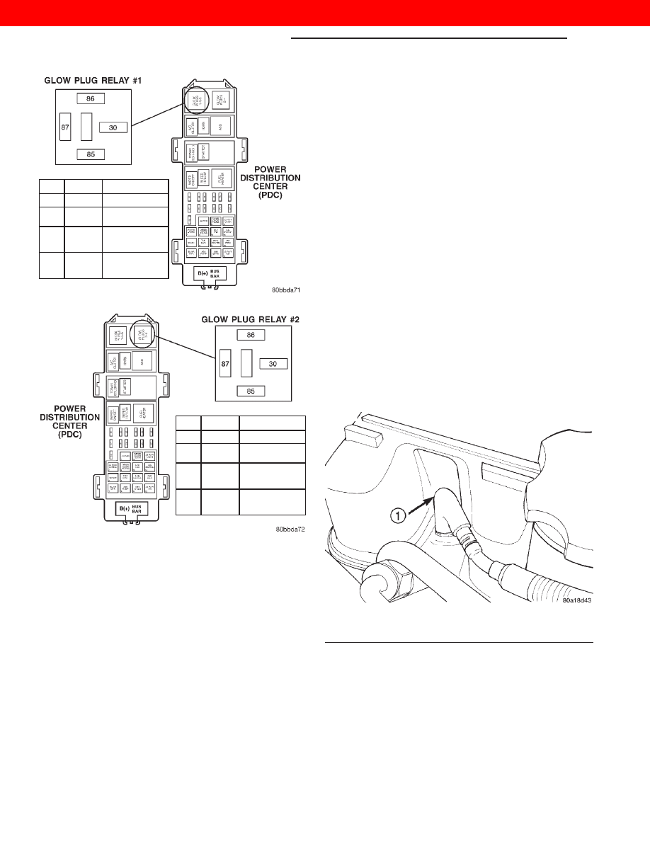
CAV
COLOR
FUNCTION
30
RD/DB
FUSED B(+)
85
DB/WT
FUSED ASD
RELAY OUTPUT
86
WT
GLOW PLUG
RELAY #1
CONTROL
87
GY
GLOW PLUG
RELAY #1
OUTPUT
Fig. 13 Glow Plug Relay #1 Location
CAV
COLOR
FUNCTION
30
VT/RD
FUSED B(+)
85
DB/WT
FUSED ASD
RELAY OUTPUT
86
LB/WT
GLOW PLUG
RELAY #2
CONTROL
87
GY/YL
GLOW PLUG
RELAY #2
OUTPUT
Fig. 14 Glow Plug Relay #2 Location
Fig. 15 Wiring Connection at Glow Plug
1 – GLOW PLUG ELECTRICAL CONNECTOR
14 - 32
FUEL SYSTEM—3.1L DIESEL ENGINE
WJ
DIAGNOSIS AND TESTING (Continued)
2000 JEEP GRAND CHEROKEE