Jeep Grand Cherokee WJ. Manual - part 391
(17) Install and connect the five high–pressure fuel
lines to the fuel injection pump. Also connect fuel
lines at the fuel injectors. For procedures, refer to
High–Pressure Fuel Lines in this group.
(18) Install electrical connector at engine coolant
temperature sensor.
(19) Connect electrical connector at fuel shutdown
solenoid.
(20) Connect the main engine wiring harness to
the glow plugs.
(21) Connect the fuel timing solenoid pigtail har-
ness to the engine wiring harness.
(22) Connect the overflow valve/banjo fitting (fuel
return line assembly). Replace copper gaskets before
installing.
(23) Connect the rubber fuel return and supply
hoses to metal lines at pump. Tighten hose clamps to
2 N·m (20 in. lbs.) torque.
(24) Install the generator assembly. Refer to Group
8C, Charging System for the procedure.
(25) Install the engine accessory drive belt. Refer
to Group 7, Cooling System for the procedure.
(26) Position the gasket and Install the intake air
duct on the intake manifold. Torque the bolts to 27
N·m (20 ft. lbs.).
(27) Install the intercooler outlet hose on the inter-
cooler.
(28) Connect the negative battery cable.
(29) Start the engine and bring to normal operat-
ing temperature.
(30) Check for fuel leaks.
FUEL INJECTORS
Four fuel injectors are used on each engine. Of
these four, two different types are used. The fuel
injector used on cylinder number one is equipped
with a fuel injector sensor (Fig. 36). The other three
fuel injectors are identical. Do not place the fuel
injector equipped with the fuel injector sensor
into any other location except the cylinder
number one position.
REMOVAL
(1) Disconnect negative battery cable at battery.
(2) Thoroughly clean the area around the injector
with compressed air.
(3) Remove the fuel drain hoses (tubes) at each
injector (Fig. 37) being serviced. Each of these hoses
is slip–fit to the fitting on injector.
(4) Remove the high–pressure fuel line at injector
being removed. Refer to High–Pressure Fuel Lines in
this group for procedures.
(5) Remove the injector using special socket tool
number VM.1012B. When removing cylinder number
one injector, thread the wiring harness through the
access hole on the special socket (Fig. 38).
(6) Remove and discard the copper washer (seal) at
bottom of injector (Fig. 36).
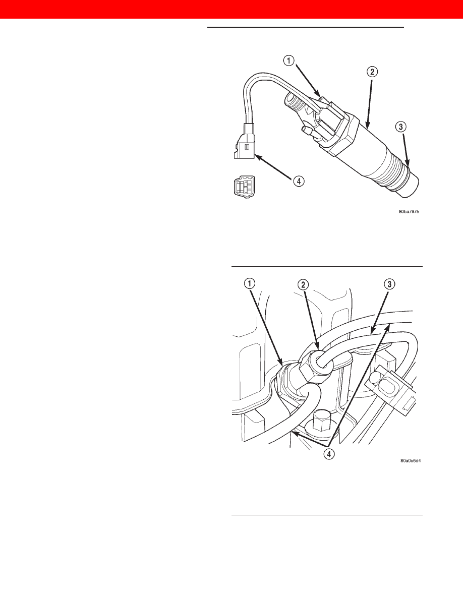
Fig. 36 Fuel Injector Sensor — #1 Cylinder
1 – NEEDLE MOVEMENT SENSOR
2 – FUEL INJECTOR (NUMBER 1 CYLINDER ONLY)
3 – COPPER WASHER
4 – SENSOR CONNECTOR
Fig. 37 Fuel Injector—Typical
1 – FUEL INJECTOR
2 – LINE FITTING
3 – HIGH-PRESSURE FUEL LINE
4 – FUEL DRAIN TUBES
14 - 20
FUEL SYSTEM—3.1L DIESEL ENGINE
WJ
REMOVAL AND INSTALLATION (Continued)
2000 JEEP GRAND CHEROKEE