Jeep Grand Cherokee WJ. Manual - part 387


  Index      Jeep     Jeep Grand Cherokee WJ - service repair manual 2001 year


Search            


Content   ..  385  386  387  388   ..


Jeep Grand Cherokee WJ. Manual - part 387


FUEL SHUTDOWN SOLENOID

DESCRIPTION

The fuel shutdown solenoid is controlled and

operated by the ECM.

The fuel shutdown (shut-off) solenoid is used to

electrically shut off the diesel fuel supply to the high-
pressure

fuel

injection

pump.

The

solenoid

is

mounted to the rear of the injection pump.

The solenoid controls starting and stopping of the

engine regardless of the position of the accelerator
pedal. When the ignition (key) switch is OFF, the
solenoid is shut off and fuel flow is not allowed to the
fuel injection pump. When the key is placed in the
ON or START positions, fuel supply is allowed at the
injection pump.

FUEL INJECTION PUMP

The fuel injection pump is a mechanical distribu-

tor–type, Bosch VP36 series (Fig. 3). A gear on the
end of the injection pump shaft meshes with the
drive gear at the front of engine. The pump is
mechanically timed to the engine. The ECM can
make adjustments to the timing of the injection
pump.

The injection pump contains the fuel shutdown

solenoid, fuel temperature sensor, control sleeve sen-
sor, fuel quantity actuator and the fuel timing sole-
noid (Fig. 3).

In the electronically controlled injection pump, the

pump plunger works the same as the pump plunger
in a mechanically controlled injection pump, but the
amount of fuel and the time the fuel is injected is

controlled by the vehicle’s ECM, instead of by a
mechanical governor assembly. A solenoid controlled
by the ECM is used in place of the mechanical gov-
ernor assembly, and it moves a control sleeve inside
the pump that regulates the amount of fuel being
injected. There is no mechanical connection between
the accelerator pedal and the electronically controlled
injection pump. Instead, a sensor connected to the
accelerator pedal sends a signal to the ECM that rep-
resents the actual position of the accelerator pedal.
The ECM uses this input, along with input from
other sensors to move the control sleeve to deliver
the appropriate amount of fuel. This system is known
as “Drive-By-Wire”

The actual time that the fuel is delivered is very

important to the diesel combustion process. The ECM
monitors outputs from the engine speed sensor (fly-
wheel position in degrees), and the fuel injector sen-
sor (mechanical movement within the #1 cylinder
fuel injector). Outputs from the Accelerator Pedal
Position sensor, engine speed sensor (engine rpm)
and engine coolant temperature sensor are also used.
The ECM will then compare its set values to these
outputs to electrically adjust the amount of fuel tim-
ing (amount of advance) within the injection pump.
This is referred to as “Closed Loop” operation. The
ECM monitors fuel timing by comparing its set value
to when the injector #1 opens. If the value is greater
than a preset value a fault will be set.

Actual electric fuel timing (amount of advance) is

accomplished by the fuel timing solenoid mounted to
the bottom of the injection pump (Fig. 3). Fuel timing
will be adjusted by the ECM, which controls the fuel
timing solenoid.

An overflow valve is attached into the fuel return

line at the rear of the fuel injection pump (Fig. 3).
This valve serves two purposes. One is to ensure that
a certain amount of residual pressure is maintained
within the pump when the engine is switched off.
This will prevent the fuel timing mechanism within
the injection pump from returning to its zero posi-
tion. The other purpose is to allow excess fuel to be
returned to the fuel tank through the fuel return
line. The pressure values within this valve are preset
and can not be adjusted.

The fuel injection pump supplies high–pressure

fuel of approximately 45,000 kPa (6526 psi) to each
injector in precise metered amounts at the correct
time.

For mechanical injection pump timing, refer to

Fuel Injection Pump Timing in the Service Proce-
dures section of this group.

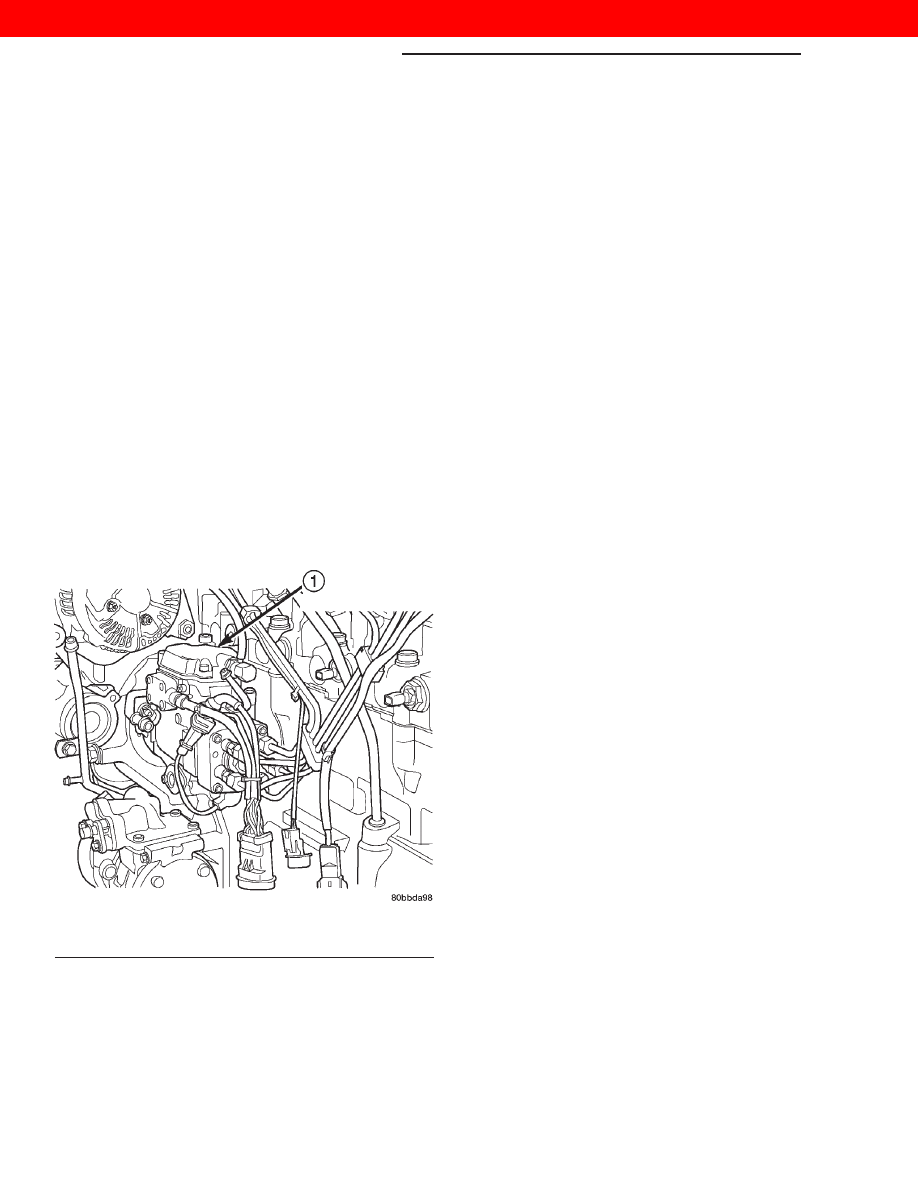
Fig. 3 Fuel Injection Pump

1 – FUEL INJECTION PUMP ASSEMBLY

14 - 4

FUEL SYSTEM—3.1L DIESEL ENGINE

WJ

DESCRIPTION AND OPERATION (Continued)

2000 JEEP GRAND CHEROKEE

FUEL INJECTORS

Fuel drain tubes (Fig. 4) are used to route excess

fuel back to the overflow valve at the rear of the
injection pump. This excess fuel is then returned to
the fuel tank through the fuel return line.

The injectors are connected to the fuel injection

pump by the high– pressure fuel lines. A separate
injector is used for each of the five cylinders. An
injector containing a sensor (Fig. 5) is used on the
cylinder number one injector. This injector is called
instrumented injector #1 or needle movement sensor.
It is used to tell the ECM when the #1 injector’s
internal spring-loaded valve seat has been forced
open by pressurized fuel being delivered to the cylin-
der, which is at the end of its compression stroke.
When the instrumented injector’s valve seat is force
open, it sends a small voltage spike pulse to the
ECM. This tells the ECM that cylinder #1 is firing. It
is not used with the other four injectors.

Fuel enters the injector at the fuel inlet (top of

injector) and is routed to the needle valve bore. When
fuel pressure rises to approximately 15,000–15,800
kPa (2175–2291 psi), the needle valve spring tension
is overcome. The needle valve rises and fuel flows
through the spray holes in the nozzle tip into the
combustion chamber. The pressure required to lift
the needle valve is the injector opening pressure set-
ting. This is referred to as the “pop-off” pressure set-
ting.

Fuel pressure in the injector circuit decreases after

injection. The injector needle valve is immediately
closed by the needle valve spring and fuel flow into
the combustion chamber is stopped. Exhaust gases
are prevented from entering the injector nozzle by
the needle valve.

A copper washer (gasket) is used at the base of

each injector (Fig. 5) to prevent combustion gases
from escaping.

Fuel injector firing sequence is 1–2–4–5–3.

FUEL TUBES/LINES/HOSES AND CLAMPS—
LOW-PRESSURE TYPE

DESCRIPTION

Also refer to the proceeding section on Quick–Con-

nect Fittings.

Inspect all hose connections such as clamps, cou-

plings and fittings to make sure they are secure and
leaks are not present. The component should be
replaced immediately if there is any evidence of deg-
radation that could result in failure.

Never attempt to repair a plastic fuel line/tube or a

quick–connect fitting. Replace complete line/tube as
necessary.

Avoid contact of any fuel tubes/hoses with other

vehicle components that could cause abrasions or
scuffing. Be sure that the fuel lines/tubes are prop-
erly routed to prevent pinching and to avoid heat
sources.

Fig. 4 Fuel Injectors and Drain Tubes

1 – FUEL DRAIN TUBES
2 – FUEL INJECTORS
3 – FITTING AT PUMP

Fig. 5 Fuel Injector Sensor

1 – NEEDLE MOVEMENT SENSOR
2 – FUEL INJECTOR (NUMBER 1 CYLINDER ONLY)
3 – COPPER WASHER
4 – SENSOR CONNECTOR

WJ

FUEL SYSTEM—3.1L DIESEL ENGINE

14 - 5

DESCRIPTION AND OPERATION (Continued)

2000 JEEP GRAND CHEROKEE

The lines/tubes/hoses are of a special construction.

If it is necessary to replace these lines/tubes/hoses,
use only original equipment type.

The hose clamps used to secure the rubber hoses

are of a special rolled edge construction. This con-
struction is used to prevent the edge of the clamp
from cutting into the hose. Only these rolled edge
type clamps may be used in this system. All other
types of clamps may cut into the hoses and cause
fuel leaks.

Where a rubber hose is joined to a metal tube

(staked), do not attempt to repair. Replace entire
line/tube assembly.

Use new original equipment type hose clamps.

Tighten hose clamps to 2 N·m (20 in. lbs.) torque.

QUICK-CONNECT FITTINGS—LOW PRESSURE
TYPE

DESCRIPTION

Different types of quick-connect fittings are used to

attach various fuel system components. These are: a
single-tab type, a two-tab type or a plastic retainer
ring type (Fig. 6). Refer to Quick-Connect Fittings in
the Removal/Installation section for more informa-
tion.

CAUTION: The interior components (o-rings, spac-
ers) of quick-connect fitting are not serviced sepa-
rately, but new pull tabs are available for some
types. Do not attempt to repair damaged fittings or
fuel lines/tubes. If repair is necessary, replace the
complete fuel tube assembly.

HIGH-PRESSURE FUEL LINES

DESCRIPTION

CAUTION: The high–pressure fuel lines must be
held securely in place in their holders. The lines
cannot contact each other or other components. Do
not attempt to weld high–pressure fuel lines or to
repair lines that are damaged. Only use the recom-
mended lines when replacement of high–pressure
fuel line is necessary.

High–pressure fuel lines deliver fuel under pres-

sure of up to approximately 45,000 kPa (6526 PSI)
from the injection pump to the fuel injectors. The
lines expand and contract from the high–pressure
fuel pulses generated during the injection process. All
high–pressure fuel lines are of the same length and
inside diameter. Correct high–pressure fuel line
usage and installation is critical to smooth engine
operation.

WARNING: USE

EXTREME

CAUTION

WHEN

INSPECTING FOR HIGH–PRESSURE FUEL LEAKS.
INSPECT FOR HIGH–PRESSURE FUEL LEAKS WITH
A SHEET OF CARDBOARD. HIGH FUEL INJECTION
PRESSURE CAN CAUSE PERSONAL INJURY IF
CONTACT IS MADE WITH THE SKIN.

FUEL DRAIN TUBES

These rubber tubes are low–pressure type.
Some excess fuel is continually vented from the

fuel injection pump. During injection, a small amount
of fuel flows past the injector nozzle and is not
injected into the combustion chamber. This fuel
drains into the fuel drain tubes (Fig. 7) and back to
the tee banjo fitting, which is connected to the same
line as the overflow valve, which allows a variable
quantity to return to the fuel tank. The overflow
valve is calibrated to open at a preset pressure.
Excess fuel not required by the pump to maintain the
minimum pump cavity pressure is then returned
through the overflow valve and on to the fuel tank
through the fuel return line.

Fig. 6 Plastic Retainer Ring-Type Fitting

1 – FUEL TUBE
2 – QUICK CONNECT FITTING
3 – PUSH
4 – PLASTIC RETAINER
5 – PUSH
6 – PUSH
7 – PUSH
8 – PUSH

14 - 6

FUEL SYSTEM—3.1L DIESEL ENGINE

WJ

DESCRIPTION AND OPERATION (Continued)

2000 JEEP GRAND CHEROKEE

FUEL HEATER

DESCRIPTION

The fuel heater is used to prevent diesel fuel from

waxing and plugging the fuel filter during cold
weather operation. The fuel heater is located in the
bottom plastic bowl of the fuel filter/water separator
(Fig. 8).

The element inside the heater assembly is made of

a Positive Temperature Coefficient (PTC) material,
and has power applied to it by the fuel heater relay
anytime the ignition key is in the “on” position. PTC
material has a high resistance to current flow when
its temperature is high, which means that it will not
generate heat when the temperature is above a cer-
tain value. When the temperature is below 7°C (45°
F), the resistance of the PTC element is lowered, and
allows current to flow through the fuel heater ele-
ment warming the fuel. When the temperature is
above 29°C (85° F), the PTC element’s resistance
rises, and current flow through the heater element
stops.

Voltage to operate the fuel heater is supplied from

the ignition (key) switch and through the fuel heater
relay. Refer to the following Fuel Heater Relay for
additional information. The fuel heater and fuel
heater relay are not controlled by the Power-
train Control Module (ECM).

FUEL HEATER RELAY

DESCRIPTION

Voltage to operate the fuel heater is supplied from

the ignition (key) switch through the fuel heater
relay. The PCM or ECM is not used to control
this relay.

The fuel heater relay is located in the PDC. The

PDC is located next to the battery in the engine com-
partment. For the location of the relay within the
PDC, refer to label on PDC cover.

DIAGNOSIS AND TESTING

GENERAL INFORMATION

This section of the group will cover a general diag-

nosis of diesel engine fuel system components.

Diagnostic Trouble Codes: Refer to On-Board

Diagnostics in Group 25, Emission Control System
for a list of Diagnostic Trouble Codes (DTC’s) for cer-
tain fuel system components.

VISUAL INSPECTION

A visual inspection for loose, disconnected, or incor-

rectly routed wires and hoses should be made before
attempting to diagnose or service the diesel fuel
injection system. A visual check will help find these
conditions. It also saves unnecessary test and diag-
nostic time. A thorough visual inspection of the fuel
injection system includes the following checks:

Fig. 7 Fuel Drain Tubes

1 – FUEL DRAIN TUBES
2 – FUEL INJECTORS
3 – FITTING AT PUMP

Fig. 8 Fuel Heater Temperature Sensor and Element

Location

1 – TERMINAL 2
2 – FUEL HEATER
3 – TERMINAL 1

WJ

FUEL SYSTEM—3.1L DIESEL ENGINE

14 - 7

DESCRIPTION AND OPERATION (Continued)

2000 JEEP GRAND CHEROKEE


Content   ..  385  386  387  388   ..