Jeep Grand Cherokee WJ. Manual - part 383


  Index      Jeep     Jeep Grand Cherokee WJ - service repair manual 2001 year


Search            


Content   ..  381  382  383  384   ..


Jeep Grand Cherokee WJ. Manual - part 383


THROTTLE POSITION SENSOR (TPS)—4.7L
V-8 ENGINE

REMOVAL

The TPS is located on the throttle body.
(1) Remove air duct and air resonator box at throt-

tle body.

(2) Disconnect TPS electrical connector (Fig. 23).
(3) Remove two TPS mounting bolts (screws) (Fig.

27).

(4) Remove TPS from throttle body.

INSTALLATION

The throttle shaft end of throttle body slides into a

socket in TPS (Fig. 28). The TPS must be installed so
that it can be rotated a few degrees. If sensor will
not rotate, install sensor with throttle shaft on other
side of socket tangs. The TPS will be under slight
tension when rotated.

(1) Install TPS and two retaining bolts.
(2) Tighten bolts to 7 N·m (60 in. lbs.) torque.
(3) Manually operate throttle control lever by hand

to check for any binding of TPS.

(4) Connect TPS electrical connector to TPS.
(5) Install air duct/air box to throttle body.

IDLE AIR CONTROL (IAC) MOTOR—4.0L
ENGINE

The IAC motor is located on the throttle body.

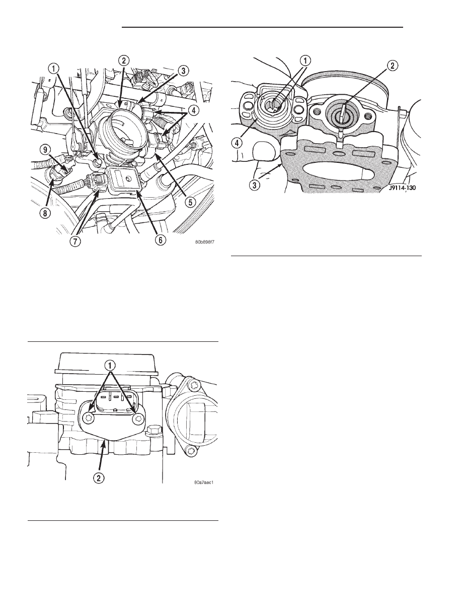
Fig. 24 TPS Electrical Connector—4.0L Engine

1 – MOUNTING BOLTS (4)
2 – THROTTLE BODY
3 – IAC MOTOR
4 – ELEC. CONN.
5 – TPS
6 – MAP SENSOR
7 – ELEC. CONN.
8 – IAT SENSOR
9 – ELEC. CONN.

Fig. 25 TPS Mounting Screws—4.0L Engine

1 – MOUNTING SCREWS
2 – TPS

Fig. 26 Throttle Position Sensor Installation—4.0L

Engine

1 – TANGS
2 – THROTTLE SHAFT
3 – THROTTLE BODY
4 – TPS

14 - 52

FUEL SYSTEM

WJ

REMOVAL AND INSTALLATION (Continued)

REMOVAL

(1) Remove air duct and air resonator box at throt-

tle body.

(2) Disconnect electrical connector from IAC motor

(Fig. 24).

(3) Remove two mounting bolts (screws) (Fig. 29).
(4) Remove IAC motor from throttle body.

INSTALLATION

(1) Install IAC motor to throttle body.
(2) Install and tighten two mounting bolts (screws)

to 7 N·m (60 in. lbs.) torque.

(3) Install electrical connector.
(4) Install air cleaner duct/air box to throttle body.

IDLE AIR CONTROL (IAC) MOTOR—4.7L V–8
ENGINE

The IAC motor is located on the throttle body.

REMOVAL

(1) Remove air duct and air resonator box at throt-

tle body.

(2) Disconnect electrical connector from IAC motor

(Fig. 23).

Fig. 27 TPS Mounting Bolts—4.7L V–8 Engine

1 – THROTTLE BODY
2 – TPS
3 – IAC MOTOR
4 – IAT SENSOR
5 – MOUNTING SCREWS

Fig. 28 TPS Installation—4.7L V–8 Engine

1 – THROTTLE BODY
2 – LOCATING TANGS
3 – THROTTLE POSITION SENSOR
4 – SOCKET
5 – THROTTLE SHAFT

Fig. 29 Mounting Bolts (Screws)—IAC Motor—4.0L

Engine

1 – IDLE AIR CONTROL MOTOR
2 – MOUNTING SCREWS

WJ

FUEL SYSTEM

14 - 53

REMOVAL AND INSTALLATION (Continued)

(3) Remove two mounting bolts (screws) (Fig. 27).
(4) Remove IAC motor from throttle body.

INSTALLATION

(1) Install IAC motor to throttle body.
(2) Install and tighten two mounting bolts (screws)

to 7 N·m (60 in. lbs.) torque.

(3) Install electrical connector.
(4) Install air duct/air box to throttle body.

MANIFOLD ABSOLUTE PRESSURE (MAP)
SENSOR—4.0L ENGINE

The MAP sensor is mounted to the side of the

throttle body (Fig. 24). An L-shaped rubber fitting is
used to connect the MAP sensor to throttle body (Fig.
30).

REMOVAL

(1) Remove air cleaner duct and air resonator box

at throttle body.

(2) Remove

two

MAP

sensor

mounting

bolts

(screws) (Fig. 30).

(3) While removing MAP sensor, slide the rubber

L-shaped fitting (Fig. 30) from the throttle body.

(4) Remove rubber L-shaped fitting from MAP sen-

sor.

INSTALLATION

(1) Install rubber L-shaped fitting to MAP sensor.
(2) Position sensor to throttle body while guiding

rubber fitting over throttle body vacuum nipple.

(3) Install MAP sensor mounting bolts (screws).

Tighten screws to 3 N·m (25 in. lbs.) torque.

(4) Install air cleanerduct/air box.

MANIFOLD ABSOLUTE PRESSURE (MAP)
SENSOR—4.7L V–8 ENGINE

The MAP sensor is located on the front of the

intake manifold (Fig. 31). An o-ring seals the sensor
to the intake manifold.

REMOVAL

(1) Disconnect electrical connector at sensor.
(2) Clean area around MAP sensor.
(3) Remove 2 sensor mounting bolts (Fig. 31).
(4) Remove MAP sensor from intake manifold.

INSTALLATION

(1) Clean MAP sensor mounting hole at intake

manifold.

(2) Check MAP sensor o-ring seal for cuts or tears.
(3) Position sensor into manifold.
(4) Install MAP sensor mounting bolts (screws).

Tighten screws to 3 N·m (25 in. lbs.) torque.

(5) Connect electrical connector.

POWERTRAIN CONTROL MODULE (PCM)

The PCM is located on the cowl panel in right/rear

side of engine compartment (Fig. 32).

Fig. 30 Rubber L-Shaped Fitting—MAP Sensor-to-

Throttle Body—4.0L Engine

1 – THROTTLE BODY
2 – MAP SENSOR
3 – RUBBER FITTING
4 – MOUNTING SCREWS (2)

Fig. 31 MAP and ECT Sensor Locations—4.7L V–8

Engine

1 – ECT SENSOR
2 – MOUNTING BOLTS (2)
3 – MAP SENSOR
4 – INTAKE MANIFOLD

14 - 54

FUEL SYSTEM

WJ

REMOVAL AND INSTALLATION (Continued)

REMOVAL

To avoid possible voltage spike damage to PCM,

ignition key must be off, and negative battery cable
must be disconnected before unplugging PCM connec-
tors.

(1) Disconnect negative battery cable at battery.
(2) If equipped, remove Transmission Control Mod-

ule (TCM).

(3) Remove coolant reserve/overflow tank.
(4) Remove cover over electrical connectors. Cover

snaps onto PCM.

(5) Carefully unplug three 32–way connectors at

PCM.

(6) Remove three PCM bracket-to-body mounting

nuts (Fig. 33).

(7) Remove

PCM/PCM

bracket

assembly

from

vehicle.

(8) Remove 3 PCM-to-PCM bracket bolts (screws)

(Fig. 34).

INSTALLATION

(1) Check pins in three 32–way electrical connec-

tors for damage. Repair as necessary.

(2) Install PCM to its mounting bracket. Tighten

three mounting bolts to 3 N·m (25 in. lbs.) torque.

(3) Install PCM/PCM bracket to body. Install 3

nuts and tighten 9 N·m (80 in. lbs.) torque.

(4) Install three 32–way connectors.
(5) Install cover over electrical connectors. Cover

snaps onto PCM.

(6) Install coolant reserve/overflow tank.
(7) If equipped, install Transmission Control Mod-

ule (TCM).

(8) Connect negative cable to battery.
(9) Use the DRB scan tool to reprogram new PCM

with vehicles original Identification Number (VIN)
and original vehicle mileage.

Fig. 32 Powertrain Control Module (PCM) Location

1 – PCM
2 – COOLANT TANK

Fig. 33 Powertrain Control Module (PCM) 32–Way

Connectors

1 – 3 32–WAY CONNECTORS
2 – PCM/BRACKET ASSEMBLY
3 – BRACKET NUTS (3)

Fig. 34 Powertrain Control Module (PCM) Mounting

Bracket

1 – PCM BRACKET
2 – PCM
3 – PCM-TO-BRACKET SCREWS (3)

WJ

FUEL SYSTEM

14 - 55

REMOVAL AND INSTALLATION (Continued)


Content   ..  381  382  383  384   ..