Jeep Grand Cherokee WJ. Manual - part 364
(6) Coat the oxygen sensor with anti-seize com-
pound. Install the sensor and tighten the nut to 48
N·m (35 ft. lbs.) torque (Fig. 8) (Fig. 7).
(7) Lower the vehicle.
(8) Start the engine and inspect for exhaust leaks
and exhaust system contact with the body panels.
Adjust the alignment, if needed.
(9) After initial start-up, check the engine exhaust
manifold to exhaust pipe nuts for proper torque.
CATALYTIC CONVERTER
REMOVAL
WARNING: IF TORCHES ARE USED WHEN WORK-
ING ON THE EXHAUST SYSTEM, DO NOT ALLOW
THE FLAME NEAR THE FUEL LINES.
(1) Raise and support the vehicle.
(2) Saturate the bolts and nuts with heat valve
lubricant. Allow 5 minutes for penetration.
(3) Remove exhaust clamp from the catalytic con-
verter and exhaust pipe connection (Fig. 14).
(4) Remove exhaust clamp from the catalytic con-
verter and muffler connection (Fig. 14).
(5) Disconnect oxygen sensor wiring (Fig. 14).
(6) Heat the exhaust pipe, catalytic converter and
muffler connections with a torch until the metal
becomes cherry red.
(7) While the metal is still cherry red, twist the
catalytic converter back and forth to separate it from
the exhaust pipe and the muffler (Fig. 15).
INSTALLATION
(1) Position the exhaust clamp over the exhaust
pipe/catalytic converter connection (Fig. 14). Tighten
the nuts to 61 N·m (45 ft. lbs.) torque.
(2) Install the muffler onto the catalytic converter
until the alignment tab is inserted into the align-
ment slot.
(3) Install the exhaust clamp at the muffler and
catalytic converter connection (Fig. 14). Tighten the
clamp nuts to 47 N·m (35 ft. lbs.) torque.
(4) Connect oxygen sensor wiring (Fig. 14).
(5) Lower the vehicle.
(6) Start the engine and inspect for exhaust leaks
and exhaust system contact with the body panels.
Adjust the alignment, if needed.
MUFFLER AND TAILPIPE
REMOVAL
All original equipment exhaust systems are manu-
factured with the tailpipe welded to the muffler. Ser-
vice replacement mufflers and tailpipes are either
clamped together or welded together.
WARNING: IF TORCHES ARE USED WHEN WORK-
ING ON THE EXHAUST SYSTEM, DO NOT ALLOW
THE FLAME NEAR THE FUEL LINES.
(1) Raise and support the vehicle.
(2) Saturate the bolts and nuts with heat valve
lubricant. Allow 5 minutes for penetration.
(3) Remove the exhaust clamp from the catalytic
converter and muffler connection (Fig. 16).
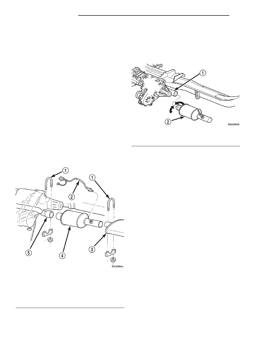
Fig. 14 Exhaust Pipe-to-Catalytic Converter-to-
Muffler Connection
1 – EXHAUST CLAMP ASSEMBLY
2 – OXYGEN SENSOR
3 – MUFFLER
4 – CATALYTIC CONVERTER
5 – EXHAUST PIPE
Fig. 15 Catalytic Converter—Removal
1 – EXHAUST PIPE
2 – CATALYTIC CONVERTER
11 - 10
EXHAUST SYSTEM
WJ
REMOVAL AND INSTALLATION (Continued)