Jeep Grand Cherokee WJ. Manual - part 358


  Index      Jeep     Jeep Grand Cherokee WJ - service repair manual 2001 year


Search            


Content   ..  356  357  358  359   ..


Jeep Grand Cherokee WJ. Manual - part 358


INSTALLATION

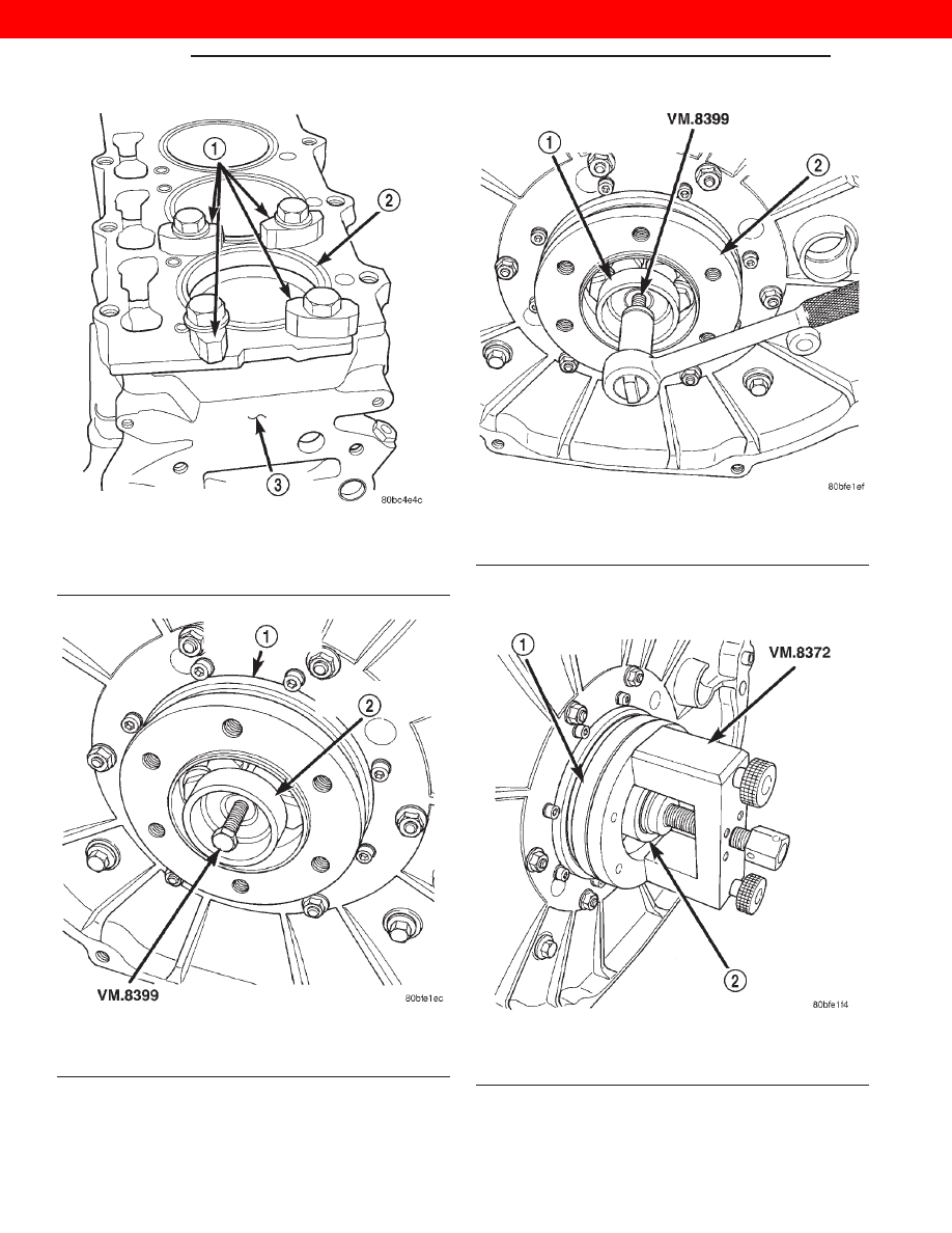
(1) Place the transmission pilot bushing into the

flexplate adapter hub.

(2) Install special tool VM-8372 on the flexplate

adapter hub (Fig. 108).

(3) Tighten the center bolt on special tool VM-8372

to install the transmission pilot bushing.

Fig. 105 Liner Clamp Location

1 – VM.1016
2 – CYLINDER LINER
3 – CYLINDER BLOCK

Fig. 106 Transmission Pilot Bushing

1 – FLEXPLATE ADAPTER HUB
2 – TRANSMISSION PILOT BUSHING

Fig. 107 Transmission Pilot Bushing Removal

1 – TRANSMISSION PILOT BUSHING
2 – FLEXPLATE ADAPTER HUB

Fig. 108 VM-8372

1 – FLEXPLATE ADAPTER HUB
2 – TRANSMISSION PILOT BUSHING

9 - 54

ENGINE

WJ

REMOVAL AND INSTALLATION (Continued)

2000 JEEP GRAND CHEROKEE

(4) Once

the

transmission

pilot

bushing

is

installed, remove the special tool VM-8372.

(5) Use special tool VM-8390 to make sure pilot

bushing is installed to proper depth (Fig. 109). Be
sure that the outside edges of special tool
VM-8390

make

contact

with

the

flexplate

adapter hub. If contact is not made remove the
transmission pilot bushing and check for debris
in the flexplate adapter hub. Then reinstall the
transmission pilot bushing into the flexplate
adapter hub.

CRANKSHAFT AND MAIN BEARINGS

REMOVAL

(1) Disconnect the negative battery cable.
(2) Remove the engine from vehicle. Refer to

engine removal and installation in this section.

(3) Install the engine on an engine stand.

(4) Remove the accessary drive system.
(5) Remove the cylinder heads. Refer to cylinder

head removal and installation in this section.

(6) Remove the oil pan and oil pick-up.
(7) Remove the pistons and connecting rods.
(8) Remove the vibration damper. Refer to vibra-

tion damper removal and installation in this section.

(9) Remove the timing gear cover. Refer to timing

gear cover removal and installation in this section.

(10) Remove the oil pump and vacuum pump from

block.

(11) Install special tool VM.1004 onto crankshaft

over gear (Fig. 110).

(12) Remove the main bearing oil feed and crank-

shaft support locators from block.

(13) Remove the flexplate and adaptor plate from

engine block.

(14) Remove the thrust bearings from rear main

bearing carrier.

(15) Slide the crankshaft and bearing carriers

rearward to rear of cylinder block. Remove crank-
shaft from the rear of the cylinder block.

Fig. 109 Transmission Pilot Bushing Gauge

VM-8390

1 – TRANSMISSION PILOT BUSHING
2 – FLEXPLATE ADAPTER HUB

Fig. 110 Crankshaft Special Tool VM.1004

1 – TOOL

WJ

ENGINE

9 - 55

REMOVAL AND INSTALLATION (Continued)

2000 JEEP GRAND CHEROKEE

(16) Mark the carriers for assembly and remove

the bolts, two for each carrier. Separate the two
halves of each carrier, remove from the crankshaft
and temporarily re-assemble the carriers (Fig. 111).

(17) Install the Crankshaft Bearing Remover/In-

staller VM.1002 on the front main bearing (Fig. 112).

(18) Using the VM.1002 pull the front main bear-

ing out of the cylinder block (Fig. 112).

INSTALLATION

NOTE: Be sure that the oil hole in the main bearing
lines up with the oil gallery hole in the cylinder
block.

(1) Using the VM.1002 push the front main bear-

ing into the cylinder block (Fig. 113).

(2) Fit the main bearing supports together. Torque

to 44 N·m (32 ft. lbs.)

(3) Check internal diameter of bearings.

(4) If internal diameter of original bearing is being

checked and figures are not within specifications,
new bearings must be used.

Fig. 111 Crankshaft and Carrier Bearing Assembly

1 – CRANKSHAFT SUPPORT
2 – CRANKSHAFT MAIN BEARING HALVE
3 – CRANKSHAFT MAIN BEARING HALVE
4 – CRANKSHAFT SUPPORT BOLTS
5 – CRANKSHAFT GEAR
6 – CRANKSHAFT
7 – CRANKSHAFT KEY

Fig. 112 Crankshaft Front Main Bearing Removal

1 – CYLINDER BLOCK
2 – VM.1002

Fig. 113 Crankshaft Front Main Bearing Installation

1 – FRONT CRANKSHAFT MAIN BEARING
2 – CYLINDER BLOCK
3 – VM.1002

9 - 56

ENGINE

WJ

REMOVAL AND INSTALLATION (Continued)

2000 JEEP GRAND CHEROKEE

(5) Check the crankshaft main bearing journals to

bearing clearances. Clearances of main bearings is.03
to.088mm (.0011 to.0035 in.).

NOTE: Assemble engine according to sequence
described, thus saving time and preventing dam-
ages to engine components. Clean parts with a suit-
able solvent and dry them with compressed air
before assembly. Use new gaskets where applicable
and torque wrenches for correct tightening of com-
ponents.

(6) Thoroughly clean crankcase and oil passages,

and blow dry with compressed air.

(7) Install new main bearing shells in each of the

carrier halves. Assemble the carriers to the crank-
shaft

journals,

ensuring

that

the

carriers

are

installed in their original locations. Secure each car-
rier with the two bolts tightening evenly to 44 N·m
(32 ft. lbs.).

(8) Slide special tool VM.1004 over the crankshaft

gear and, insert the crankshaft and support assembly
into the crankcase in the same manner used for
removal.

(9) Align the holes in the lower supports, with the

center of the crankcase webs (Fig. 114).

(10) Secure each support assembly to the crank-

case with the main bearing oil feed and support loca-
tors. Torque to 54 N·m (40 ft. lbs).

(11) Install the rear main bearing support onto

crankshaft ensuring arrow on bearing support aligns
with vertical web in center of crankcase.

(12) Install the rear oil seal.

(13) Install the new O-rings in adaptor plate.
(14) Install the adaptor plate to block. Torque nuts

to 28 N·m (20 ft. lbs.).

(15) Install the Allen bolts through adaptor plate

to rear main bearing support. Torque to 11 N·m (97
in. lbs.).

(16) Position the flexplate adapter hub and O-ring

on crankshaft and align bolt holes.

NOTE: For purposes of checking crankshaft end
play, used adapter hub bolts may be used. Final
assembly requires new adapter hub bolts.

(17) Install 2 adapter hub bolts, 180° apart, and

tighten bolts to 20 N·m plus 60° (15 ft. lbs.) plus 60°.

(18) Attach dial indicator to engine block.
(19) Move crankshaft toward front of engine and

zero indicator.

(20) Move crankshaft toward the rear of engine

and record measurement.

(21) Subtract specified crankshaft end play from

figure obtained. Crankshaft end play 0.08 to 0.28 mm
(.0060 to.0119 in.).

(22) Select thrust washers which will give correct

end play.

(23) Remove tools and adapter hub.
(24) Lubricate thrust washer halves and fit them

into the rear main bearing carrier.

(25) Ensure that crankshaft end and adapter hub

mating surfaces are clean and dry. Install “O” ring in
adapter hub groove.

(26) To verify correct end play, install 2 adapter

hub bolts 180° apart, and tighten bolts to 20 N·m
plus 60° (15 ft. lbs. plus 60°).

(27) Measure crankshaft end play with a dial

gauge. Crankshaft end play should not exceed 0.08 to
0.28 mm (.0060 to.0119 in.) (Fig. 115).

CAUTION: Use NEW adapter hub bolts for the fol-
lowing procedure.

(28) Install a new O-ring on adapter hub. Install

adapter hub on crankshaft. The 6 adapter hub bolts
must be tightened as follows:

a. Lubricate and install the 6 new adapter hub

bolts.

b. Torque the 6 adapter hub bolts to 50 N·m (36 ft.

lbs.) starting one bolt and following with the opposite
one (cross tightening) until completion, in a clockwise
direction..

c. Loosen one bolt at a time and tighten to 20 N·m

(14 ft. lbs.) plus 75° using the cross tightening
method.

(29) Install the pistons and connecting rod assem-

blies. Refer to piston and connecting rods removal
and installation in this section.

Fig. 114 Main Bearing Support Alignment

WJ

ENGINE

9 - 57

REMOVAL AND INSTALLATION (Continued)

2000 JEEP GRAND CHEROKEE


Content   ..  356  357  358  359   ..