Jeep Grand Cherokee WJ. Manual - part 354


  Index      Jeep     Jeep Grand Cherokee WJ - service repair manual 2001 year


Search            


Content   ..  352  353  354  355   ..


Jeep Grand Cherokee WJ. Manual - part 354


Refer to Group 11, Exhaust System and Turbo-
charger for the proper procedure.

(7) Then, tighten the 14mm bolts with special tool

VM.1019 in the following manner:

(8)

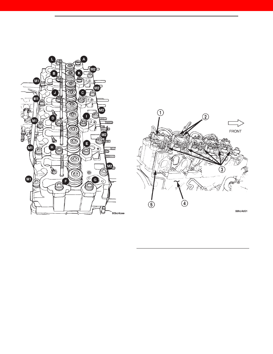
1st Phase: Tightening Head Bolts (Fig. 67).

Central bolts (A-L): Tighten all bolts, starting with
bolt I then J-K-L-A-B-C-D-E-F-G-H, to 30 N·m.
Tighten all bolts an additional 70°, starting with bolt
A and continuing in alphabetical order. Finally,
tighten all bolts an additional 70°, starting again
with bolt A and continuing in alphabetical order.

(9) Tighten the 12mm bolts in the following man-

ner:

(10) Side bolts (M1-M2): Tighten M1 bolts to 30

N·m, then rotate them 85° (

65). Tighten M2 bolts to

30 N·m, then rotate them 85° (

65).

NOTE: If vehicle is equipped with A/C do not install
A/C lines to compressor and charge A/C till Phase 2
is complete.

(11)

2nd Phase: After 20 minutes of engine oper-

ation at operating temperature, allow engine to cool

down completely. Then retorque the head bolts as fol-
lows:

(12) Central bolts A-L: Completely back off bolts

one-by-one and then retighten to 30 N·m plus 130°
(

65°). Then proceed in the same way, bolt by bolt,

following alphabetical order, as indicated.

(13) Side

bolts

M1-M2:

Without

slackening,

torque bolts M1 then bolts M2 to 90 N·m (66 ft. lbs.).

(14) Torque intake nuts to 28 N·m (20 ft. lbs.) and

exhaust manifolds nuts to 32 N·m (24 ft. lbs.) after
completing the cylinder head torquing procedure.

(15) Install the oil feed lines for the rocker arm

assemblies. Torque oil feed lines to 13 N·m (115 in.
lbs.) (Fig. 68).

(16) Install the oil feed line retaining clip at rear

of the cylinder head (Fig. 69). Torque bolt to 5.5 N·m
(4 ft. lbs.).

(17) Install the push rods. (Fig. 70).

WARNING: During the installation of the rocker arm
assemblies it is possible to cause valve interfer-
ence between the piston and valve if the piston is
near Top Dead Center (TDC). This is due to the slow
bleed down rate of the tappets when adjusting the
rocker arm assemblies. Follow the procedure below
to ensure that engine damage does not occur.

• Install the rocker arm assemblies in the same

order as removed (Fig. 70).

Fig. 67 Engine Cylinder Head Bolt Tightening

Sequence

Fig. 68 Oil Feed Lines

1 – ROCKER ARM ASSEMBLIES
2 – ROCKER ARM NUTS
3 – CYLINDER HEAD OIL SUPPLY LINE
4 – ENGINE BLOCK
5 – CYLINDER HEADS

9 - 38

ENGINE

WJ

REMOVAL AND INSTALLATION (Continued)

2000 JEEP GRAND CHEROKEE

• Bring piston # 1 to Top Dead Center.

• At this point tighten the rocker arm nuts for cyl-

inder # 2–3–4–5. Torque nuts to 27 N·m (20 ft. lbs.).

• Slowly rotate the crankshaft 90° clockwise or

counterclockwise, then tighten the rocker arm nuts
for cylinder # 1. Torque nuts to 27 N·m (20 ft. lbs.).

(19) Install the cylinder head cover. Torque bolts to

15 N·m (133 in. lbs.) (Fig. 71).

(20) Connect the crankcase breather hose to front

of cylinder head cover.

(21) Connect the injector sensor wire and the glow

plug hot lead.

(22) Install the turbocharger oil feed line. Torque

banjo bolts to 27 N·m (20 ft. lbs).

(23) Install

the

turbocharger

oil

return

line.

Torque bolts to 11 N·m (97 in. lbs.).

(24) Install the water manifold. Torque bolts to 12

N·m (106 in. lbs.).

(25) Raise the vehicle on hoist.
(26) Install the exhaust pipe to turbocharger.

Torque bolts to 32 N·m (23 ft. lbs.).

(27) Lower vehicle form hoist.

(28) Install

the

exhaust

manifold/turbocharger

heat shield. Torque bolts to 11 N·m (8 ft. lbs.).

(29) Install the heater core supply lines.
(30) Install the EGR valve/heater core supply line

retaining bolts. Torque bolts to 28 N·m (20 ft. lbs.).

(31) Install the intercooler hose to turbocharger.
(32) Install the air cleaner hose to turbocharger.
(33) Install the oil breather hose to air cleaner

hose.

(34) Connect the recover hose to water manifold.
(35) Install the fuel injectors using special tool

VM.1012B. Refer to Group 14, Fuel System for pro-
cedures.

(36) Install the fuel supply lines to injectors.

Torque nuts to 19 N·m (14 ft. lbs.).

(37) Connect the A/C lines to compressor and

install bracket on cylinder head cover.

(38) Connect the upper radiator hose.
(39) Install the intake manifold elbow and inter-

cooler hose.

Fig. 69 Cylinder Head Oil Supply Line Retaining Clip

1 – CYLINDER HEAD OIL SUPPLY LINE RETAINING CLIP
2 – EXHAUST MANIFOLD
3 – CYLINDER HEAD OIL SUPPLY LINE
4 – REAR OF CYLINDER HEADS
5 – CYLINDER HEAD COVER

Fig. 70 Rocker Arm Assemblies

1 – CYLINDER HEADS
2 – ROCKER ARM RETAINING NUTS
3 – ROCKER ARM SPRING PLATE
4 – ROCKER ARM ASSEMBLIES

WJ

ENGINE

9 - 39

REMOVAL AND INSTALLATION (Continued)

2000 JEEP GRAND CHEROKEE

(40) Connect the negative cable battery.
(41) Evacuate and charge the air conditioning sys-

tem. Refer to Group 24, Heater and Air Conditioning.

(42) Fill the cooling system. Check for leaks.

WARNING: USE EXTREME CAUTION WHEN THE
ENGINE IS OPERATING. DO NOT STAND IN DIRECT
LINE WITH THE FAN. DO NOT PUT HANDS NEAR
THE PULLEYS, BELTS OR FAN. DO NOT WEAR
LOOSE CLOTHING.

(43) Operate the engine with the radiator cap off.

Inspect for leaks and continue operating the engine
until the thermostat opens. Add coolant, if required.

NOTE: The one piece steel type head gasket does
not require retorqueing.

VIBRATION DAMPER

REMOVAL

(1) Disconnect the negative battery cable.

(2) Remove the fan and set fan inside fan shroud

then remove fan shroud and fan as an assembly.

(3) Remove the accessary drive belt. Refer to

Group 7, Cooling System for procedure.

(4) Remove the vibration damper nut.
(5) Install special tool VM.1000-A to remove vibra-

tion damper (Fig. 72).

INSTALLATION

(1) Install the vibration damper and align with

key way.

(2) Install the vibration damper nut. Torque nut to

196 N·m (147 ft. lbs.).

(3) Install the accessary drive belt. Refer to Group

7, Cooling System for procedure.

(4) Connect the negateive battery cable.

TIMING GEAR COVER OIL SEAL

REMOVAL

(1) Disconnect the negative battery cable.
(2) Remove the vibration damper. Refer to vibra-

tion damper removal and installation procedure in
this section.

CAUTION: Use care when removing the old seal.
Be sure not to damage the timing gear cover.

(3) Pry out the old seal.

Fig. 71 Cylinder Head Cover

1 – WATER MANIFOLD RETAINING BOLTS
2 – WATER MANIFOLD
3 – CYLINDER HEAD COVER
4 – CYLINDER HEAD COVER RETAINING BOLTS

Fig. 72 VM.1000–A

1 – TIMING GEAR COVER
2 – VIBRATION DAMPER
3 – VM.1000–A
4 – AUTOMATIC BELT TENSIONER

9 - 40

ENGINE

WJ

REMOVAL AND INSTALLATION (Continued)

2000 JEEP GRAND CHEROKEE

INSTALLATION

The seating diameter must be 68.000 - 68.030 mm.

(1) Install

the

new

seal

using

special

tool

VM.1015A (Fig. 74).

(2) Install the vibration damper. Refer to vibration

damper removal and installation procedure in this
section.

(3) Connect the negative battery cable.

TIMING GEAR COVER

REMOVAL

(1) Disconnect the negative battery cable.
(2) Remove the fan and set fan inside fan shroud

then remove fan shroud and fan as an assembly.

(3) Remove the accessary drive belt. Refer to

Group 7, Cooling System for procedure.

(4) Remove the vibration damper nut.
(5) Install special tool VM.1000-A to remove the

vibration damper (Fig. 75).

(6) Remove the fan pulley (Fig. 76).

NOTE: The idler pulleys have left hand threaded
bolts.

(7) Remove the idler pulley and bracket (Fig. 76).
(8) Remove the automatic belt tensioner (Fig. 76).
(9) Remove the Power steering pump pulley (Fig.

76).

(10) Remove the timing gear cover.

Fig. 73 Timing Gear Cover Oil Seal

Fig. 74 VM.1015–A

1 – TIMING GEAR COVER
2 – VM.1015A

Fig. 75 VM.1000–A

1 – TIMING GEAR COVER
2 – VIBRATION DAMPER
3 – VM.1000–A
4 – AUTOMATIC BELT TENSIONER

WJ

ENGINE

9 - 41

REMOVAL AND INSTALLATION (Continued)

2000 JEEP GRAND CHEROKEE


Content   ..  352  353  354  355   ..