Jeep Grand Cherokee WJ. Manual - part 331


  Index      Jeep     Jeep Grand Cherokee WJ - service repair manual 2001 year


Search            


Content   ..  329  330  331  332   ..


Jeep Grand Cherokee WJ. Manual - part 331


INSTALLATION

(1) Position the insulator mount and install the

through bolt.

(2) Lower the transmission enough to install the

four insulator-to-transmission mounting bolts. Torque
the bolts to 46N·m (34 ft. lbs.).

(3) Install the through bolt lock nut. Torque nut to

68N·m (50 ft. lbs.).

(4) Remove jack, lower vehicle.

STRUCTURAL COVER

REMOVAL

(1) Raise vehicle on hoist.
(2) Remove the left hand exhaust pipe from

exhaust manifold. Refer to Group 11, Exhaust Sys-
tem.

(3) Loosen the right hand exhaust manifold-to-ex-

haust pipe retaining bolts.

(4) Remove the eight bolts retaining structural

cover (Fig. 37).

(5) Pivot the exhaust pipe downward and remove

the structural cover.

INSTALLATION

CAUTION: The structural cover must be installed
as described in the following steps. Failure to do so
will cause severe damage to the cover.

(1) Position the structural cover in the vehicle.
(2) Install all four bolts retaining the cover-to-en-

gine. DO NOT tighten the bolts at this time.

(3) Install the four cover-to-transmission bolts. Do

NOT tighten at this time.

CAUTION: The structural cover must be held tightly
against both the engine and the transmission bell

housing during tightening sequence. Failure to do
so may cause damage to the cover.

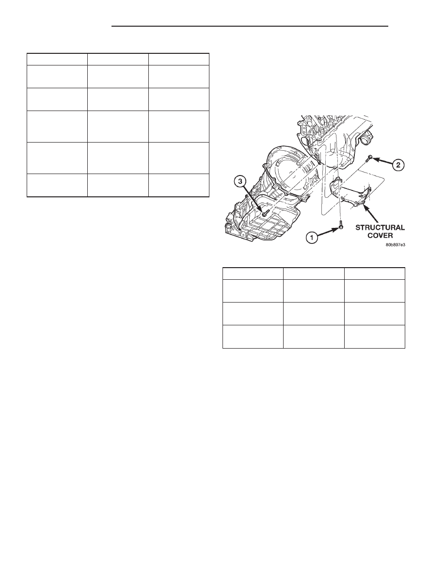
(4) Starting with the two rear cover-to-engine

bolts, tighten bolts (1) (Fig. 37) to 54 N·m (40 ft. lbs.),
then tighten bolts (2) (Fig. 37) and (3) to 54 N·m ( 40
ft. lbs.) in the sequence shown.

(5) Install the exhaust pipe on left hand exhaust

manifold.

(6) Tighten

exhaust

manifold-to-exhaust

pipe

retaining bolts to 20–26 N·m (15–20 ft. lbs.).

ENGINE

REMOVAL

(1) Disconnect the battery negative cable.
(2) Remove the front fascia. Refer to BODY for cor-

rect procedure.

(3) Raise vehicle on hoist.
(4) Remove exhaust crossover pipe from exhaust

manifolds. Refer to Group 11, Exhaust System.

(5) Disconnect two ground straps from the lower

left hand side and one ground strap from the lower
right hand side of the engine.

(6) Disconnect crankshaft position sensor. (Fig. 38)
(7) Remove structural cover. Refer to Structural

Cover in this section for procedure.

(8) Remove starter. Refer to STARTING SYSTEM.

ITEM

DESCRIPTION

TORQUE

1

NUT

45 N·m

(Qty 1)

(33 ft. lbs)

2

BOLT

46 N·m

(Qty 4)

(34 ft. lbs.)

3

BOLT

68 N·m

(Qty 2 Per

Side)

(50 ft. lbs.)

4

BOLT

46 N·m

(Qty 2 Per

Side)

(34 ft. lbs.)

5

BOLT

46 N·m

(Qty 4)

(34 ft. lbs.)

Fig. 37 Structural Cover

SEQUENCE

ITEM

TORQUE

1

BOLT

54 N·m

(Qty 4)

(40 ft. lbs.)

2

BOLT

54 N·m

(Qty 2)

(40 ft. lbs.)

3

BOLT

54 N·m

(Qty 2)

(40 ft. lbs.)

9 - 90

4.7L ENGINE

WJ

REMOVAL AND INSTALLATION (Continued)

(9) Remove rubber splash shield.
(10) Drain cooling system. Refer to COOLING

SYSTEM.

(11) Remove torque converter bolts (Automatic

Transmission Only). Refer to TRANSMISSION.

(12) Remove

transmission

to

engine

mounting

bolts.

(13) Disconnect the engine block heater power

cable from the block heater.

(14) Lower vehicle.
(15) Remove throttle body resonator assembly and

inlet hose.

(16) Disconnect throttle and speed control cables.
(17) Disconnect tube from both the left and right

side crankcase breathers, then remove the breathers
(Fig. 39).

(18) Discharge A/C system. Refer to HEATING and

AIR CONDITIONING.

(19) Remove shroud, fan assemblies and accessory

drive belt. Refer to COOLING SYSTEM for proce-
dure.

(20) Remove A/C compressor.
(21) Disconnect transmission oil cooler lines at the

radiator.

(22) Disconnect radiator lower hose at the thermo-

stat housing. Refer to Group 7.

(23) Remove A/C condenser. Refer to HEATING

and AIR CONDITIONING.

(24) Remove radiator. Refer to COOLING SYS-

TEM.

(25) Remove generator.
(26) Disconnect the two heater hoses from the tim-

ing chain cover.

(27) Disconnect engine harness at the following

points :

• Intake air temperature (IAT) sensor (Fig. 40)

• Fuel Injectors

• Throttle Position (TPS) Switch

• Idle Air Control (IAC) Motor

• Engine Oil Pressure Switch

• Engine Coolant Temperature (ECT) Sensor

• Manifold absolute pressure (MAP) Sensor

• Camshaft Position (CMP) Sensor

• Coil Over Plugs
(28) Release fuel rail pressure then disconnect the

fuel supply quick connect fitting at the fuel rail.
Refer to FUEL SYSTEM for procedure.

(29) Remove power steering pump and position out

of the way.

(30) Disconnect ground straps from the left side of

the engine.

(31) Install Engine Lifting Fixture Special Tool

8347 (Fig. 41) following these steps.

• Holding the lifting fixture at a slight angle, slide

the large bore in the front plate over the hex portion
of the lifting stud.

• Position the two remaining fixture arms onto

the two lifting studs in the cylinder heads.

• Pull foward and upward on the lifting fixture so

that the lifting stud rest in the slotted area below the
large bore.

• Secure the lifting fixture to the three studs

using three 7/16 – 14 N/C locknuts.

• Make sure the lifting loop in the lifting fixture is

in the last hole (closest to the throttle body) to min-
imize the angle of engine during removal.

(32) Disconnect body ground strap at the right side

cowl.

Fig. 38 Crankshaft Position Sensor

1 – CRANKSHAFT POSITION SENSOR
2 – CYLINDER HEAD COVER
3 – CAMSHAFT POSITION SENSOR
4 – RIGHT SIDE CYLINDER BLOCK

Fig. 39 Crankcase Breather Connection Points

1 – CRANKCASE BREATHERS

WJ

4.7L ENGINE

9 - 91

REMOVAL AND INSTALLATION (Continued)

NOTE: It will be necessary to support the transmis-
sion in order to remove the engine.

(33) Position a suitable jack under the transmis-

sion.

(34) Remove the engine mount through bolts.
(35) Raise engine slightly, then remove both left

and right side engine mounts from engine. Refer to
Engine Mounts—Front in this section.

(36) Remove engine from the vehicle.

INSTALLATION

(1) Position engine in the vehicle.
(2) Install both left and right side engine mounts

onto engine.

Position both the left and right side engine mount

brackets and install the through bolts and nuts.

(3) Install transmission to engine mounting bolts.

Tighten the bolts to 41 N·m (30 ft. lbs.).

(4) Remove jack from under the transmission.
(5) Remove engine lifting fixture special tool 8347

(Fig. 41).

(6) Connect ground straps on the left side of the

engine.

(7) Install power steering pump.
(8) Connect fuel supply line quick connect fitting.
(9) Connect engine harness at the following points

(Fig. 40) :

• Intake Air Temperature (IAT) Sensor

• Idle Air Control (IAC) Motor

• Fuel Injectors

• Throttle Position (TPS) Switch

• Engine Oil Pressure Switch

• Engine Coolant Temperature (ECT) Sensor

• Manifold Absolute Pressure (MAP) Sensor

• Camshaft Position (CMP) Sensor

• Coil Over Plugs
(10) Install generator.
(11) Install radiator.
(12) Install A/C condenser.
(13) Connect radiator lower hose at the thermostat

housing.

Fig. 40 Throttle Body Connection Points

1 – THROTTLE BODY
2 – TPS
3 – IAC MOTOR
4 – IAT SENSOR
5 – MOUNTING SCREWS

Fig. 41 Engine Lifting Fixture Attachment Locations

1 – ATTACHING LOCATION
2 – ADJUSTABLE HOOK
3 – SPECIAL TOOL 8347 ENGINE LIFT FIXTURE
4 – ATTACHING LOCATIONS

9 - 92

4.7L ENGINE

WJ

REMOVAL AND INSTALLATION (Continued)

(14) Connect the transmission oil cooler lines to

the radiator.

(15) Install A/C compressor. Tighten the A/C com-

pressor and generator M10 mounting bolts 40–68N·M
(30–50 ft. lbs.) and the M8 bolts 22–34 N·m (200–300
in. lbs.).

(16) Install accessory drive belt, fan assembly and

shroud.

(17) Install breathers, then connect tube to both

crankcase breathers (Fig. 39).

(18) Connect throttle and speed control cables.
(19) Install throttle body resonator assembly and

inlet hose.

(20) Raise vehicle.
(21) Connect two ground straps on the lower left

hand side of the engine and one ground strap on the
lower right side.

(22) Install torque converter bolts.
(23) Connect crankshaft position sensor (Fig. 38).
(24) Install starter.
(25) Install rubber splash shield.

CAUTION: The structural cover requires a specific
torque sequence. Failure to follow this sequence
may cause severe damage to the cover.

(26) Install structural cover. Refer to Structural

Cover in this section.

(27) Install exhaust crossover pipe.
(28) Install engine block heater power cable, If

equipped.

(29) Lower vehicle.
(30) Check and fill engine oil.
(31) Recharge the A/C system.
(32) Refill the engine cooling system.
(33) Connect the battery negative cable.
(34) Start engine and check for leaks.

INTAKE MANIFOLD

REMOVAL

(1) Disconnect negative cable from battery.
(2) Remove air cleaner housing and throttle body

resonator (Fig. 42).

(3) Disconnect throttle and speed control cables.
(4) Disconnect electrical connectors for the follow-

ing components: Refer to FUEL SYSTEM for loca-
tion.

• Manifold Absolute Pressure (MAP) Sensor

• Intake Air Temperature (IAT) Sensor

• Throttle Position (TPS) Sensor

• Coolant Temperature (CTS) Sensor

• Idle Air Control (IAC) Motor
(5) Disconnect vapor purge hose, brake booster

hose, speed control servo hose, positive crankcase
ventilation (PCV) hose.

(6) Remove accessory drive belt. Refer to COOL-

ING SYSTEM.

(7) Disconnect generator electrical connections.
(8) Unbolt the generator and move it away from

the intake manifold for clearance.

(9) Disconnect air conditioning compressor electri-

cal connections.

(10) Unbolt the air conditioning compressor and

move it away from the intake manifold for clearance.

(11) Disconnect left and right radio suppressor

straps.

(12) Disconnect and remove ignition coil towers.
(13) Remove top oil dipstick tube retaining bolt

and ground strap.

(14) Bleed fuel system. Refer to FUEL SYSTEM.
(15) Remove fuel rail.
(16) Remove throttle body assembly and mounting

bracket.

(17) Drain cooling system below coolant tempera-

ture level. Refer to COOLING SYSTEM.

(18) Remove coolant temperature sensor. Refer to

FUEl SYSTEM.

(19) Remove cowl to hood seal. Refer to BODY.
(20) Remove right side engine lifting stud.
(21) Remove intake manifold retaining fasteners,

in

(21) reverse order of tightening sequence (Fig. 43).

NOTE: Intake must be lifted upward and level in the
front and rear to clear the cowl. Interference with
the cowl will occur during removal.

(22) Remove intake manifold.

Fig. 42 Throttle Body Resonator

1 – THROTTLE BODY RESONATOR
2 – BOLT
3 – BOLT

WJ

4.7L ENGINE

9 - 93

REMOVAL AND INSTALLATION (Continued)


Content   ..  329  330  331  332   ..