Jeep Grand Cherokee WJ. Manual - part 318


  Index      Jeep     Jeep Grand Cherokee WJ - service repair manual 2001 year


Search            


Content   ..  316  317  318  319   ..


Jeep Grand Cherokee WJ. Manual - part 318


NOTE: If the valves, springs, or seals are to be
inspected/replaced at this time, refer to Valves and
Valve Springs in this section for proper inspection
procedures.

INSTALLATION

The engine cylinder head gasket is a composition

gasket. The gasket is to be installed DRY. DO NOT
use a gasket sealing compound on the gasket.

If the engine cylinder head is to be replaced and

the original valves used, measure the valve stem
diameter. Only standard size valves can be used with
a service replacement engine cylinder head unless
the replacement head valve stem guide bores are
reamed

to

accommodate

oversize

valve

stems.

Remove all carbon buildup and reface the valves.

(1) Remove the shop towels from the cylinder

bores. Coat the bores with clean engine oil.

(2) Position the engine cylinder head gasket (with

the numbers facing up) using the alignment dowels
in the cylinder block, to position the gasket.

CAUTION: Engine cylinder head bolts should be
reused only once. Replace the head bolts if they
were used before or if they have a paint dab on the
top of the bolt.

(3) With bolt No.14 held in place (tape around

bolt), install the engine cylinder head over the same
dowels used to locate the gasket. Remove the tape
from bolt No.14.

(4) Coat the threads of stud bolt No.11 with Loc-

tite 592 sealant, or equivalent.

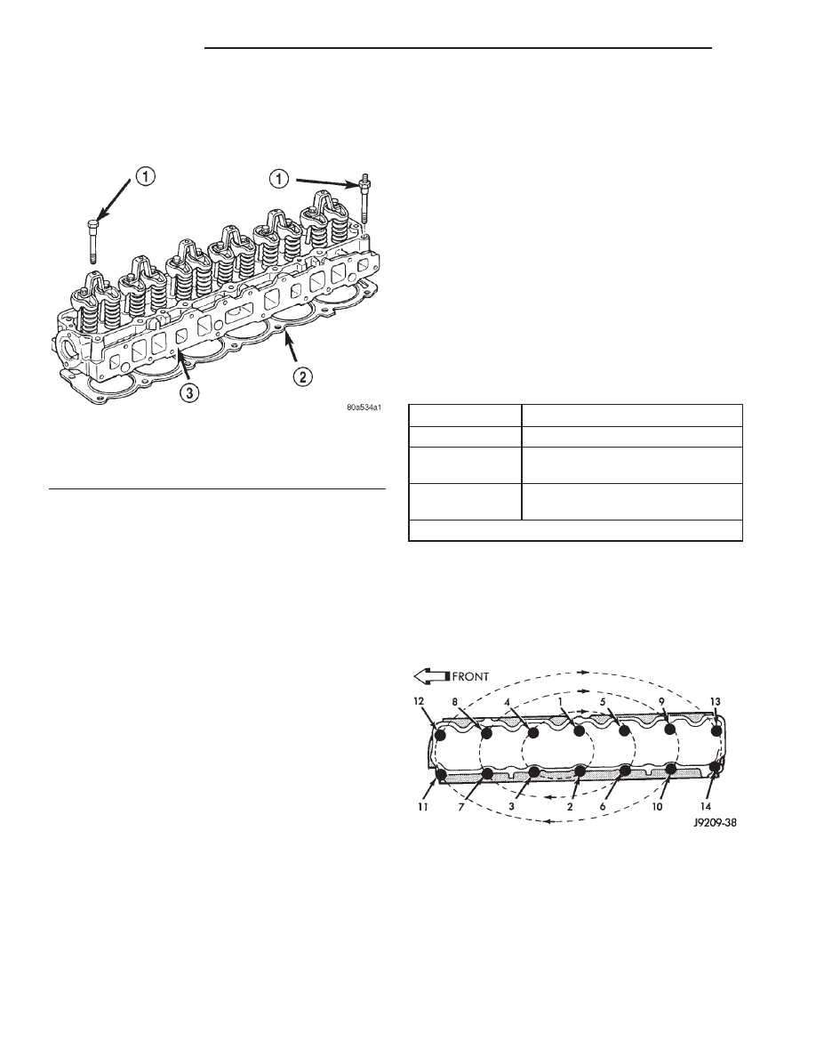
(5) Tighten the engine cylinder head bolts in

sequence according to the following procedure (Fig.
53).

CAUTION: During the final tightening sequence,
bolt No.11 will be tightened to a lower torque than
the rest of the bolts. DO NOT overtighten bolt
No.11.

(a) Tighten all bolts in sequence (1 through 14)

to 30 N·m (22 ft. lbs.) torque.

(b) Tighten all bolts in sequence (1 through 14)

to 61 N·m (45 ft. lbs.) torque.

(c) Check all bolts to verify they are set to 61

N·m (45 ft. lbs.) torque.

(d) Tighten bolts in sequence:

• Bolts 1 through 10 to 149 N·m (110 ft. lbs.)

torque.

• Bolt 11 to 135 N·m (100 ft. lbs.) torque.

• Bolts 12 through 14 to 149 N·m (110 ft. lbs.)

torque.

(e) Check all bolts in sequence to verify the cor-

rect torque.

(f) If not already done, clean and mark each bolt

with a dab of paint after tightening. Should you
encounter bolts which were painted in an earlier
service operation, replace them.

(6) Install the spark plugs and tighten to 37 N·m

(27 ft. lbs.) torque.

(7) Connect the temperature sending unit wire

connector.

(8) Install the ignition coil rail and coil rail electri-

cal connectors.

Fig. 52 Engine Cylinder Head Assembly

1 – CYLINDER HEAD BOLTS
2 – CYLINDER HEAD GASKET
3 – CYLINDER HEAD

CYLINDER HEAD BOLTS

POSITION

DESCRIPTION

1,4,5,12,13

1/2 in.-13 BOLT

8,9

1/2 in.-13 BOLT WITH DOWEL
POINT

2,3,6,7,10,11,14

1/2 in.-13 WITH 7/16 in.-14 STUD
END

All bolts are 12 point drives for rocker cover clearance

Fig. 53 Engine Cylinder Head Bolt Tightening

Sequence

9 - 38

4.0L ENGINE

WJ

REMOVAL AND INSTALLATION (Continued)

(9) Install the intake and engine exhaust mani-

folds (refer to procedures in this section).

(10) Install the fuel line and the vacuum advance

hose.

(11) Attach the power steering pump and bracket.
(12) Install the push rods, rocker arms, pivots and

bridges in the order they were removed (refer to
Rocker Arms and Push Rods in this section).

(13) Install the engine cylinder head cover.
(14) Attach the air conditioner compressor mount-

ing bracket to the engine cylinder head and block.
Tighten the bolts to 40 N·m (30 ft. lbs.) torque.

(15) Attach the air conditioning compressor to the

bracket. Tighten the bolts to 27 N·m (20 ft. lbs.)
torque.

CAUTION: The serpentine drive belt must be routed
correctly. Incorrect routing can cause the water
pump to turn in the opposite direction causing the
engine to overheat.

(16) Install the serpentine drive belt. (refer to

Group 7, Cooling System for the proper procedure).

(17) Install the air cleaner and ducting.
(18) Connect the hoses to the engine thermostat

housing and fill the cooling system to the specified
level (refer to Group 7, Cooling Systems for the
proper procedure).

(19) The automatic transmission throttle linkage

and cable must be adjusted after completing the
engine cylinder head installation (refer to Group 21,
Transmissions for the proper procedures).

(20) Install the temperature sending unit and con-

nect the wire connector.

(21) If equipped with air conditioning, install A/C

compressor and charge A/C system (refer to Group 24
Heating and Air Conditioning).

(22) Connect negative cable to battery.

WARNING: USE EXTREME CAUTION WHEN THE
ENGINE IS OPERATING. DO NOT STAND IN DIRECT
LINE WITH THE FAN. DO NOT PUT HANDS NEAR
THE PULLEYS, BELTS OR FAN. DO NOT WEAR
LOOSE CLOTHING.

(23) Operate the engine with the radiator cap off.

Inspect for leaks and continue operating the engine
until the engine thermostat opens. Add coolant, if
required.

VALVES AND VALVE SPRINGS

This procedure is done with the engine cylinder

head removed from the block.

REMOVAL

(1) Remove the engine cylinder head from the cyl-

inder block.

(2) Use

Valve

Spring

Compressor

Tool

MD-998772A and compress each valve spring.

(3) Remove the valve locks, retainers, springs and

valve stem oil seals. Discard the oil seals.

(4) Use a smooth stone or a jewelers file to remove

any burrs on the top of the valve stem, especially
around the groove for the locks.

(5) Remove the valves, and place them in a rack in

the same order as removed.

INSTALLATION

(1) Thoroughly clean the valve stems and the valve

guide bores.

(2) Lightly lubricate the stem.
(3) Install the valve in the original valve guide

bore.

(4) Install the replacement valve stem oil seals on

the valve stems. If the 0.381 mm (0.015 inch) over-
size valve stems are used, oversize oil seals are
required.

(5) Position the valve spring and retainer on the

engine cylinder head and compress the valve spring
with Valve Spring Compressor Tool MD-998772A.

(6) Install the valve locks and release the tool.
(7) Tap the valve spring from side to side with a

hammer to ensure that the spring is properly seated
at the engine cylinder head. Also tap the top of the
retainer to seat the valve locks.

(8) Install the engine cylinder head.

HYDRAULIC TAPPETS

Retain all the components in the same order as

removed.

REMOVAL

(1) Remove the engine cylinder head (Refer to cyl-

inder head r&i in this section).

(2) Remove the push rods.
(3) Remove the tappets through the push rod open-

ings in the cylinder block with a Hydraulic Valve
Tappet Removal/Installation Tool (Fig. 54).

INSTALLATION

It is not necessary to charge the tappets with

engine oil. They will charge themselves within a very
short period of engine operation.

(1) Dip each tappet in Mopar Engine Oil Supple-

ment, or equivalent.

(2) Use Hydraulic Valve Tappet Removal/Installa-

tion Tool to install each tappet in the same bore from
where it was originally removed.

(3) Install the cylinder head assy (Refer to cylinder

head r&i in this section).

(4) Install the push rods in their original locations.

WJ

4.0L ENGINE

9 - 39

REMOVAL AND INSTALLATION (Continued)

(5) Install the rocker arms and bridge and pivot

assemblies at their original locations. Loosely install
the capscrews at each bridge.

(6) Tighten the capscrews alternately, one turn at

a time, to avoid damaging the bridges. Tighten the
capscrews to 28 N·m (21 ft. lbs.) torque.

(7) Pour the remaining Mopar Engine Oil Supple-

ment, or equivalent over the entire valve actuating
assembly. The Mopar Engine Oil Supplement, or
equivalent must remain with the engine oil for at
least 1 609 km (1,000 miles). The oil supplement
need not be drained until the next scheduled oil
change.

(8) Install the engine cylinder head cover.

VIBRATION DAMPER

REMOVAL

(1) Disconnect negative cable from battery.
(2) Remove the serpentine drive belt and fan

shroud. Refer to Group 7, Cooling Systems for the
procedures.

(3) Remove the vibration damper retaining bolt

and washer.

(4) Use Vibration Damper Removal Tool 7697 to

remove the damper from the crankshaft (Fig. 55).

INSTALLATION

(1) Apply Mopar Silicone Rubber Adhesive Sealant

to the keyway in the crankshaft and insert the key.
With the key in position, align the keyway on the
vibration damper hub with the crankshaft key and
tap the damper onto the crankshaft.

(2) Install the vibration damper retaining bolt and

washer.

(3) Tighten the damper retaining bolt to 108 N·m

(80 ft. lbs.) torque.

(4) Install the serpentine drive belt. (Refer to

Group 7, Cooling Systems for the proper specifica-
tions and procedures).

(5) Connect negative cable to battery.

TIMING CASE COVER

REMOVAL

(1) Disconnect negative cable from battery.
(2) Remove the vibration damper.
(3) Remove the fan and hub assembly and remove

the fan shroud.

(4) Remove the accessory drive brackets that are

attached to the timing case cover.

(5) Remove the A/C compressor (if equipped) and

generator bracket assembly from the engine cylinder
head and move to one side.

(6) Remove the oil pan-to-timing case cover bolts

and timing case cover-to-cylinder block bolts.

(7) Remove the timing case cover and gasket from

the engine.

(8) Pry the crankshaft oil seal from the front of the

timing case cover (Fig. 56).

INSTALLATION

Clean the timing case cover, oil pan and cylinder

block gasket surfaces.

(1) Install a new crankshaft oil seal in the timing

case cover. The open end of the seal should be toward
the inside of the cover. Support the cover at the seal
area while installing the seal. Force it into position
with Seal Installation Tool 6139.

(2) Position the gasket on the cylinder block.
(3) Position the timing case cover on the oil pan

gasket and the cylinder block.

Fig. 54 Hydraulic Valve Tappet Removal—

Installation Tool

1 – HYDRAULIC TAPPET REMOVAL TOOL
2 – CYLINDER BLOCK

Fig. 55 Vibration Damper Removal Tool 7697

1 – VIBRATION DAMPER REMOVAL TOOL
2 – WRENCH

9 - 40

4.0L ENGINE

WJ

REMOVAL AND INSTALLATION (Continued)

(4) Insert Timing Case Cover Alignment and Seal

Installation Tool 6139 in the crankshaft opening in
the cover (Fig. 57).

(5) Install the timing case cover-to-cylinder block

and the oil pan-to-timing case cover bolts.

(6) Tighten the 1/4 inch cover-to-block bolts to 7

N·m (60 in. lbs.) torque. Tighten the 5/16 inch front
cover-to-block bolts to 22 N·m (192 in. lbs.) torque.
Tighten the oil pan-to-cover 1/4 inch bolts to 9.5 N·m
(84 in. lbs.) torque.

(7) Remove the cover alignment tool.
(8) Apply a light film of engine oil on the vibration

damper hub contact surface of the seal.

(9) Apply Mopar Silicone Rubber Adhesive Sealant

to the keyway in the crankshaft and insert the key.
With the key inserted in the keyway in the crank-
shaft, install the vibration damper, washer and bolt.
Lubricate and tighten the bolt to 108 N·m (80 ft. lbs.)
torque.

(10) Install the A/C compressor (if equipped) and

generator bracket assembly.

(11) Install the engine fan and hub assembly and

shroud.

(12) Install the serpentine drive belt.
(13) Connect negative cable to battery.

TIMING CHAIN AND SPROCKETS

REMOVAL

(1) Disconnect negative cable from battery.
(2) Remove the fan and shroud.
(3) Remove the serpentine drive belt.
(4) Remove the crankshaft vibration damper.
(5) Remove the timing case cover.
(6) Rotate crankshaft until the “0” timing mark is

closest to and on the center line with camshaft
sprocket timing mark (Fig. 58).

(7) Remove the oil slinger from the crankshaft.
(8)

Remove the camshaft sprocket bolt and

washer (Fig. 59).

(9) Remove

the

crankshaft

sprocket,

camshaft

sprocket and timing chain as an assembly.

Fig. 56 Timing Case Cover Components

1 – TIMING CASE COVER
2 – OIL SLINGER
3 – CRANKSHAFT OIL SEAL
4 – VIBRATION DAMPER PULLEY

Fig. 57 Timing Case Cover Alignment and Seal

Installation Tool 6139

1 – TIMING CASE COVER ALIGNMENT AND SEAL

INSTALLATION TOOL

Fig. 58 Crankshaft—Camshaft Alignment

1 – CAMSHAFT SPROCKET
2 – TIMING MARKS
3 – CRANKSHAFT SPROCKET

WJ

4.0L ENGINE

9 - 41

REMOVAL AND INSTALLATION (Continued)


Content   ..  316  317  318  319   ..