Jeep Grand Cherokee WJ. Manual - part 165


  Index      Jeep     Jeep Grand Cherokee WJ - service repair manual 2001 year


Search            


Content   ..  163  164  165  166   ..


Jeep Grand Cherokee WJ. Manual - part 165


REMOVAL AND INSTALLATION

AUTOMATIC DAY/NIGHT MIRROR

REMOVAL

(1) Disconnect and isolate the battery negative

cable.

(2) Disconnect the overhead wire harness connec-

tor from the automatic day/night mirror connector
receptacle (Fig. 2).

(3) Remove the screw that secures the automatic

day/night mirror to the support button on the wind-
shield.

(4) Slide the automatic day/night mirror mounting

base upwards far enough to clear the support button
on the windshield.

(5) Remove the automatic day/night mirror from

the support button on the windshield.

INSTALLATION

(1) Position the automatic day/night mirror above

the support button on the windshield.

(2) Slide the automatic day/night mirror mounting

base downwards over the support button on the
windshield.

(3) Install and tighten the screw that secures the

automatic day/night mirror to the support button on
the windshield. Tighten the screw to 1.7 N·m (15 in.
lbs.).

(4) Reconnect the overhead wire harness connector

to the automatic day/night mirror connector recepta-
cle.

(5) Reconnect the battery negative cable.

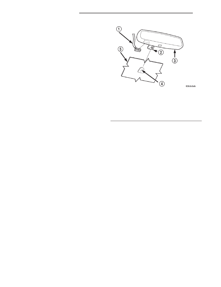
Fig. 2 Automatic Day/Night Mirror Remove/Install -

Typical

1 – CONNECTOR
2 – SCREW
3 – ELECTROCHROMATIC REAR VIEW MIRROR
4 – SUPPORT BUTTON
5 – WINDSHIELD

8T - 8

POWER MIRROR SYSTEMS

WJ

CHIME/BUZZER WARNING SYSTEMS

TABLE OF CONTENTS

page

page

DESCRIPTION AND OPERATION

CHIME WARNING SYSTEM . . . . . . . . . . . . . . . . . 1
DRIVER DOOR AJAR SWITCH . . . . . . . . . . . . . . . 3
DRIVER SEAT BELT SWITCH . . . . . . . . . . . . . . . . 3
KEY-IN IGNITION SWITCH . . . . . . . . . . . . . . . . . . 3
HEADLAMP SWITCH . . . . . . . . . . . . . . . . . . . . . . 4

DIAGNOSIS AND TESTING

CHIME WARNING SYSTEM . . . . . . . . . . . . . . . . . 4

DRIVER DOOR AJAR SWITCH . . . . . . . . . . . . . . . 4
DRIVER SEAT BELT SWITCH . . . . . . . . . . . . . . . . 5
KEY-IN IGNITION SWITCH . . . . . . . . . . . . . . . . . . 5
HEADLAMP SWITCH . . . . . . . . . . . . . . . . . . . . . . 6

REMOVAL AND INSTALLATION

CHIME WARNING SYSTEM SWITCHES . . . . . . . . 6

DESCRIPTION AND OPERATION

CHIME WARNING SYSTEM

DESCRIPTION

A chime warning system is standard factory-in-

stalled equipment on this model. The chime warning
system is designed to provide an audible warning or
feedback of various conditions that may require the
attention or awareness of the vehicle operator. The
chime warning system has access to both non-
switched and ignition switched sources of battery
current so that some audible warnings may occur at
any time, while others may only occur with the igni-
tion switch in the On or Accessory positions.

A Body Control Module (BCM) is used on this

model to control and integrate many of the electronic
functions and features included on the vehicle. One
of the functions and features that the BCM supports
is the chime warning system. The BCM contains a
chime tone generator and control logic to perform the
functions of the chime warning system. The BCM
contains a central processing unit and interfaces with
other modules in the vehicle on the Programmable
Communications Interface (PCI) data bus network.

The chime warning system includes the following

components:

• Body Control Module (BCM)

• Driver door ajar switch

• Driver seat belt switch

• Key-in ignition switch.
Refer to Body Control Module in the Description

and Operation section of Group 8E - Instrument
Panel Systems for more information on this compo-
nent. Refer to Body Control Module in the Con-
tents of Group 8W - Wiring Diagrams for complete
circuit diagrams. Following are general descriptions

of the remaining major components in the factory-in-
stalled chime warning system.

OPERATION

The chime warning system provides an audible

indication to the vehicle operator under the following
conditions:

• Fasten Seat Belt Reminder - If the driver

side seat belt is not fastened with the ignition switch
in the On position, a chime will sound for about six
seconds.

• Head Lamps On Warning - If the head or

park lamps are left on with the ignition switch Off
and the driver side front door open, a chime will
sound.

• Key In Ignition Warning - If the driver side

front door is open while the key is in the ignition
switch lock cylinder, a chime will sound.

• Tactile Beep Support - A beep tone is gener-

ated as audible confirmation that an Electronic Vehi-
cle Information Center (EVIC) button was completely
depressed, and/or that certain Sentry Key Immobi-
lizer System (SKIS) functions have been completed.

• Warning Indicator Chime - An audible alert

to the vehicle operator that supplements certain
visual warning indications displayed by the Electro-
Mechanical Instrument Cluster (EMIC) and/or the
Electronic Vehicle Information Center (EVIC).

See the owner’s manual in the vehicle glove box for

more information on the features, use and operation
of the chime warning system.

The BCM uses hard wired inputs, internal pro-

gramming, and PCI data bus chime request message
inputs to decide when a chime tone is required. This
group only covers the diagnosis and service of the
hard wired inputs used by the BCM to determine
that a chime tone should be generated. For diagnosis
of the BCM, the PCI data bus, or the other electronic

WJ

CHIME/BUZZER WARNING SYSTEMS

8U - 1

modules on the PCI data bus that send chime
request messages to the BCM, the use of a DRB scan
tool and the proper Diagnostic Procedures manual
are recommended.

Refer to Body Control Module in the Removal

and Installation section of Group 8E - Instrument
Panel Systems for the BCM service procedures. The
BCM can only be serviced by an authorized electronic
repair station. See the latest version of the Chrysler
Corporation Warranty Policies and Procedures man-
ual for a current listing of authorized electronic
repair stations.

DRIVER DOOR MODULE

The Driver Door Module (DDM) monitors the

driver door ajar switch through a hard wired circuit.
The DDM is programmed to send driver door ajar
messages over the Programmable Communications
Interface (PCI) data bus to the Body Control Module
(BCM) and the Electronic Vehicle Information Center
when it detects that the driver door is ajar. The BCM
and the EVIC are programmed to determine if any
other monitored vehicle conditions are present that
will require a chime tone (BCM) or chime tone
request message (EVIC) to be generated.

Refer to Door Module in the Description and

Operation section of Group 8P - Power Lock Systems
for more information on the DDM. Refer to Body
Control Module 
in the Description and Operation
section of Group 8E - Instrument Panel Systems for
more information on this component. Refer to Elec-
tronic Vehicle Information Center 
in the Descrip-
tion and Operation section of Group 8V - Overhead
Console Systems for more information on this compo-
nent.

ELECTRO-MECHANICAL INSTRUMENT CLUSTER

The

Electro-Mechanical

Instrument

Cluster

(EMIC) is also supported by the chime warning sys-
tem. The EMIC is programmed to send chime
request messages over the Programmable Communi-
cations Interface (PCI) data bus to the Body Control
Module (BCM) when it detects the following condi-
tions:

• Airbag indicator lamp illuminated

• Anti-lock Brake System (ABS) lamp illuminated

• Check gauges lamp illuminated for one of the

following conditions:

• Charging system voltage high or low

• Engine coolant temperature high

• Engine coolant temperature critical

• Engine oil pressure low

• Low fuel warning lamp illuminated (customer

programmable)

• Malfunction Indicator Lamp (MIL) illuminated

• Transmission oil temperature warning lamp illu-

minated.

See the owner’s manual in the vehicle glove box for

more information on the features, use and operation
of the EMIC. Refer to Instrument Cluster in the
Description and Operation section of Group 8E -
Instrument Panel Systems for more information on
the EMIC.

ELECTRONIC VEHICLE INFORMATION CENTER

The Electronic Vehicle Information Center (EVIC)

uses the chime warning system for two different
kinds of support. In addition to requesting chime
tones from the Body Control Module (BCM) as tactile
beep support, the EVIC is programmed to send chime
request messages over the Programmable Communi-
cations Interface (PCI) data bus when it detects the
following conditions:

• Door Ajar Warning - A door is ajar above a

critical speed [about 16 kilometers-per-hour (10
miles-per-hour) for the driver side front door, or
about 5 kilometers-per-hour (3 miles-per-hour) for
any other door].

• Liftgate Ajar Warning - The liftgate or lift-

gate flip-up glass is ajar above a critical speed [about
5 kilometers-per-hour (3 miles-per-hour)].

• Low Coolant Level Warning - The coolant

level in the engine coolant reservoir is low.

• Perform Service Alert - An audible alert that

a “Perform Service” reminder message is being dis-
played by the EVIC.

• Turn Signal On Warning - A turn signal

remains on for about 1.6 kilometers (one mile) with
no decrease in speed or throttle opening

• Washer Fluid Low Warning - The fluid level

in the washer reservoir is low.

See the owner’s manual in the vehicle glove box for

more information on the features, use and operation
of the EVIC. Refer to Electronic Vehicle Informa-
tion Center 
in the Description and Operation sec-
tion of Group 8V - Overhead Console Systems for
more information on the EVIC.

SENTRY KEY IMMOBILIZER SYSTEM

The Sentry Key Immobilizer System (SKIS) also

uses tactile beep support from the chime warning
system. The Sentry Key Immobilizer Module (SKIM)
is programmed to send chime request messages over
the Programmable Communications Interface (PCI)
data bus to the Body Control Module (BCM) to pro-
vide audible confirmation that:

• The SKIM has been successfully placed in the

Customer Learn mode.

• A new Sentry key transponder has been success-

fully programmed by the SKIM.

8U - 2

CHIME/BUZZER WARNING SYSTEMS

WJ

DESCRIPTION AND OPERATION (Continued)

See the owner’s manual in the vehicle glove box for

more information on the features, use and operation
of the SKIS. Refer to Sentry Key Immobilizer Sys-
tem 
in the Description and Operation section of
Group 8Q - Vehicle Theft/Security Systems for more
information on the SKIS.

DRIVER DOOR AJAR SWITCH

DESCRIPTION

The driver door ajar switch is concealed within and

integral to the driver side front door latch unit. The
driver door ajar switch is actuated by the front door
latch mechanism, and is hard wired between a body
ground and the Driver Door Module (DDM) through
the driver side front door wire harness.

The driver door ajar switch cannot be adjusted or

repaired and, if faulty or damaged, the driver side
front door latch unit must be replaced. Refer to
Front Door Latch in the Removal and Installation
section of Group 23 - Body for the service procedures.
Refer to Door Module in the Power Lock System
section of Group 8P - Power Lock Systems for more
information on this component. For complete circuit
diagrams, refer to Interior Lighting in the Con-
tents of Group 8W - Wiring Diagrams.

OPERATION

The driver door ajar switch closes a path to ground

for the DDM when the driver side front door is
opened, and opens the ground path when the driver
side front door is closed. The DDM reads the switch
status through an internal pull-up, then sends the
proper switch status messages to other electronic
modules over the Programmable Communications
Interface (PCI) data bus network. The driver door
ajar switch status message is used by the Body Con-
trol Module (BCM) as an input for chime warning
system operation.

DRIVER SEAT BELT SWITCH

DESCRIPTION

The driver seat belt switch is concealed within and

integral to the driver seat belt buckle-half unit. The
driver seat belt switch is actuated by the seat belt
buckle mechanism, and is hard wired between a body
ground and the Body Control Module (BCM) through
the left body wire harness with manual seats, or
through the driver side power seat and left body wire
harnesses with power seats.

The driver seat belt switch cannot be adjusted or

repaired and, if faulty or damaged, the entire driver
seat belt buckle-half unit must be replaced. Refer to
Front Shoulder Belt/Buckle in the Removal and

Installation section of Group 23 - Body for the service
procedures. Refer to Body Control Module in the
Description and Operation section of Group 8E -
Instrument Panel Systems for more information on
this component. For complete circuit diagrams, refer
to Body Control Module in the Contents of Group
8W - Wiring Diagrams.

OPERATION

The driver seat belt switch closes a path to ground

for the BCM when the tip-half of the driver seat belt
is not fastened to the buckle-half, and opens the
ground path when the two halves of the seat belt are
fastened. The BCM monitors the driver seat belt
switch status through an internal pull-up, then sends
the proper switch status messages to other electronic
modules over the Programmable Communications
Interface (PCI) data bus network. The driver seat
belt switch status is also used by the BCM as an
input for chime warning system operation.

KEY-IN IGNITION SWITCH

DESCRIPTION

The key-in ignition switch is concealed within and

integral to the ignition switch, which is mounted on
the steering column. The key-in ignition switch is
actuated by the ignition lock cylinder mechanism,
and is hard wired between a body ground and the
Body Control Module (BCM) through the instrument
panel wire harness.

The key-in ignition switch cannot be adjusted or

repaired and, if faulty or damaged, the entire igni-
tion switch unit must be replaced. Refer to Ignition
Switch and Key Cylinder 
in the Removal and
Installation section of Group 8D - Ignition Systems
for the service procedures. Refer to Body Control
Module 
in the Description and Operation section of
Group 8E - Instrument Panel Systems for more infor-
mation on this component. For complete circuit dia-
grams, refer to Body Control Module in the
Contents of Group 8W - Wiring Diagrams.

OPERATION

The key-in ignition switch closes a path to ground

for the BCM when the ignition key is inserted in the
ignition lock cylinder, and opens the ground path
when the key is removed from the ignition lock cyl-
inder. The BCM monitors the key-in ignition switch
status through an internal pull-up, then sends the
proper switch status messages to other electronic
modules over the Programmable Communications
Interface (PCI) data bus network. The key-in ignition
switch status is also used by the BCM as an input
for chime warning system operation.

WJ

CHIME/BUZZER WARNING SYSTEMS

8U - 3

DESCRIPTION AND OPERATION (Continued)


Content   ..  163  164  165  166   ..