Jeep Grand Cherokee WJ. Manual - part 157


  Index      Jeep     Jeep Grand Cherokee WJ - service repair manual 2001 year


Search            


Content   ..  155  156  157  158   ..


Jeep Grand Cherokee WJ. Manual - part 157


(2) Insert one of the two valid Sentry Key tran-

sponders into the ignition switch and turn the igni-
tion switch to the On position.

(3) After the ignition switch has been in the On

position for about three seconds, but no more than
fifteen seconds later, cycle the ignition switch back to
the Off position. Replace the first valid Sentry Key in
the ignition lock cylinder with the second valid Sen-
try Key and turn the ignition switch back to the On
position.

(4) About ten seconds after the completion of Step

3, the SKIS indicator lamp will start to flash and a
single audible chime tone will sound to indicate that
the system has entered the “Customer Learn” pro-
gramming mode.

(5) Within about fifty seconds of entering the “Cus-

tomer Learn” programming mode, turn the ignition
switch to the Off position, replace the valid Sentry
Key with a blank Sentry Key transponder, and turn
the ignition switch back to the On position.

(6) About ten seconds after the completion of Step

5, a single audible chime tone will sound and the
SKIS indicator lamp will stop flashing and stay on
solid for about three seconds to indicate that the
blank Sentry Key transponder has been successfully
programmed. The SKIS will immediately return to
normal system operation following exit from the
“Customer Learn” programming mode.

(7) Go back to Step 2 and repeat this process for

each additional Sentry Key transponder blank to be
programmed.

If any of the above steps is not completed in the

proper sequence, or within the allotted time, the
SKIS will automatically exit the “Customer Learn”
programming mode. The SKIS will also automatically
exit the “Customer Learn” programming mode if it
sees a non-blank Sentry Key transponder when it
should see a blank, if it has already programmed
eight valid Sentry Keys, or if the ignition switch is
turned to the Off position for more than about fifty
seconds.

REMOVAL AND INSTALLATION

SENTRY KEY IMMOBILIZER MODULE

WARNING: ON VEHICLES EQUIPPED WITH AIR-
BAGS,

REFER

TO

GROUP

8M

-

PASSIVE

RESTRAINT SYSTEMS BEFORE ATTEMPTING ANY
STEERING

WHEEL,

STEERING

COLUMN,

OR

INSTRUMENT PANEL COMPONENT DIAGNOSIS OR
SERVICE. FAILURE TO TAKE THE PROPER PRE-
CAUTIONS COULD RESULT IN ACCIDENTAL AIR-
BAG DEPLOYMENT AND POSSIBLE PERSONAL
INJURY.

REMOVAL

(1) Disconnect and isolate the battery negative

cable.

(2) Remove the steering column opening cover

from the instrument panel. Refer to Steering Col-
umn Opening Cover 
in the Removal and Installa-
tion section of Group 8E - Instrument Panel Systems
for the procedures.

(3) Disconnect the instrument panel wire harness

connector from the Sentry Key Immobilizer Module
(SKIM) connector receptacle.

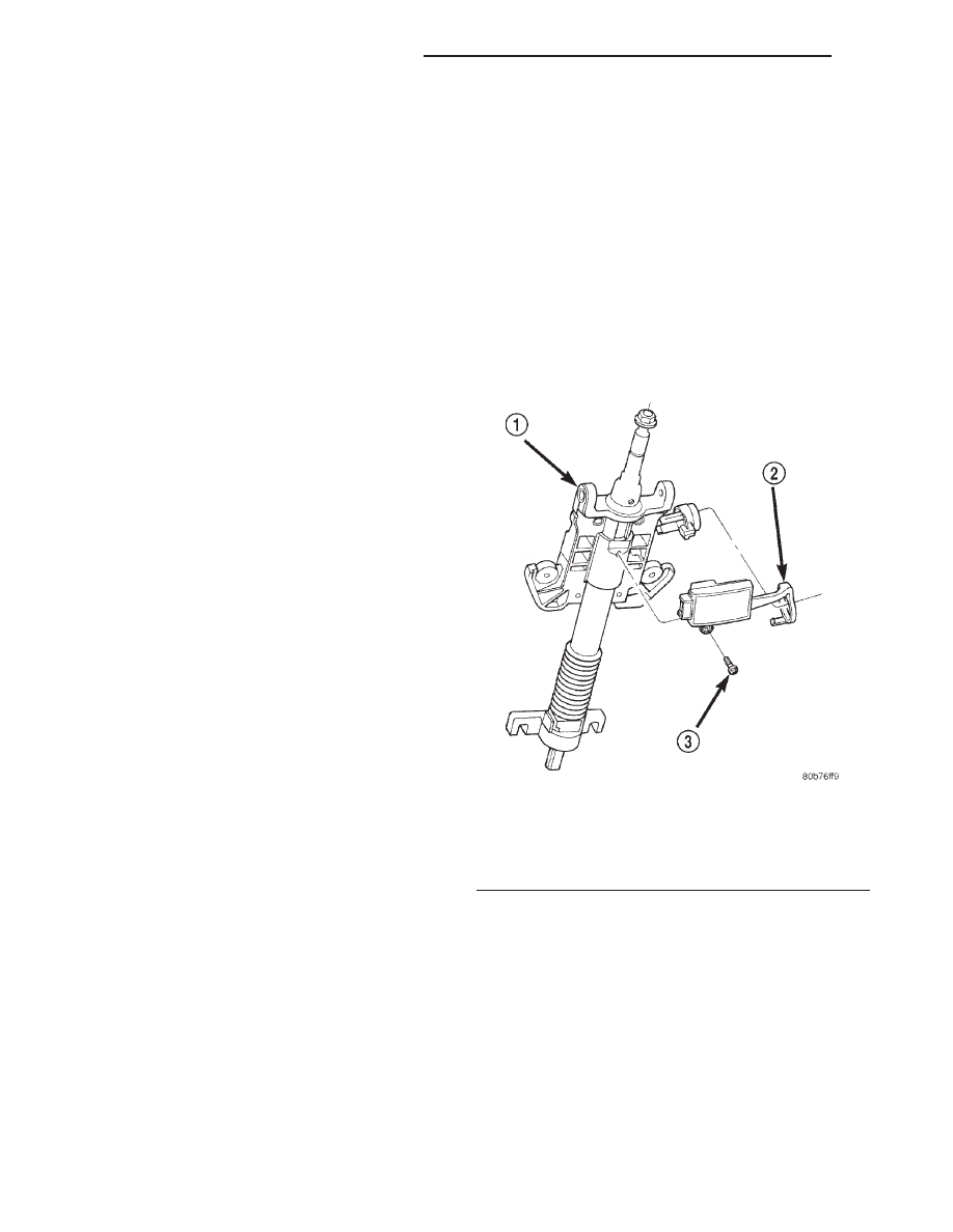
(4) Remove the one screw that secures the SKIM

to the bottom of the steering column housing
between the ignition switch and the ignition lock cyl-
inder (Fig. 2).

(5) Pull the lower right side of the fixed column

shroud away from the ignition lock cylinder far
enough to disengage the antenna ring of the SKIM
from around the ignition lock cylinder housing.

(6) Remove the SKIM from the steering column.

INSTALLATION

(1) Position the SKIM under the steering column.
(2) Pull the lower right side of the fixed column

shroud away from the ignition lock cylinder far
enough to engage the antenna ring of the SKIM
around the ignition lock cylinder housing.

Fig. 2 Sentry Key Immobilizer Module Remove/

Install

1 – STEERING COLUMN
2 – SKIM
3 – MOUNTING SCREW

8Q - 10

VEHICLE THEFT/SECURITY SYSTEMS

WJ

SERVICE PROCEDURES (Continued)

(3) Install and tighten the one screw that secures

the SKIM to the bottom of the steering column hous-
ing between the ignition switch and the ignition lock
cylinder. Tighten the screw to 3.4 N·m (30 in lbs.).

(4) Reconnect the instrument panel wire harness

connector to the SKIM connector receptacle.

(5) Install the steering column opening cover onto

the instrument panel. Refer to Steering Column

Opening Cover in the Removal and Installation sec-
tion of Group 8E - Instrument Panel Systems for the
procedures.

(6) Reconnect the battery negative cable.

WJ

VEHICLE THEFT/SECURITY SYSTEMS

8Q - 11

REMOVAL AND INSTALLATION (Continued)

POWER SEAT SYSTEMS

TABLE OF CONTENTS

page

page

POWER SEAT SYSTEM. . . . . . . . . . . . . . . . . . . . . . 1

MEMORY SYSTEM . . . . . . . . . . . . . . . . . . . . . . . . 11

POWER SEAT SYSTEM

TABLE OF CONTENTS

page

page

DESCRIPTION AND OPERATION

POWER SEAT SYSTEM . . . . . . . . . . . . . . . . . . . . . 1
POWER LUMBAR ADJUSTER . . . . . . . . . . . . . . . . 2
POWER LUMBAR SWITCH . . . . . . . . . . . . . . . . . . 2
POWER SEAT RECLINER . . . . . . . . . . . . . . . . . . . 3
POWER SEAT SWITCH . . . . . . . . . . . . . . . . . . . . . 3
POWER SEAT TRACK . . . . . . . . . . . . . . . . . . . . . . 4

DIAGNOSIS AND TESTING

POWER LUMBAR ADJUSTER . . . . . . . . . . . . . . . . 5

POWER SEAT SYSTEM . . . . . . . . . . . . . . . . . . . . . 5
POWER LUMBAR SWITCH . . . . . . . . . . . . . . . . . . 6
POWER SEAT RECLINER . . . . . . . . . . . . . . . . . . . 6
POWER SEAT SWITCH . . . . . . . . . . . . . . . . . . . . . 7
POWER SEAT TRACK . . . . . . . . . . . . . . . . . . . . . . 7

REMOVAL AND INSTALLATION

POWER LUMBAR SWITCH . . . . . . . . . . . . . . . . . . 8
POWER SEAT SWITCH . . . . . . . . . . . . . . . . . . . . . 9

DESCRIPTION AND OPERATION

POWER SEAT SYSTEM

DESCRIPTION

Driver and passenger power front seats are an

available factory-installed option for this vehicle. The
power seat system option allows the driver and front
seat passenger to electrically adjust their seating
positions for optimum control and comfort using the
power seat switches located on the outboard seat
cushion side shield of each front seat. The power seat
system receives battery current through a fuse in the
Power Distribution Center (PDC) and a circuit
breaker in the junction block so that the power seats
remain operational, regardless of the ignition switch
position.

Two power seat options are offered on this vehicle,

depending upon the model. They are as follows:

• Six-way power seat - This power seat is an

available option on Laredo models equipped with
cloth-trimmed seats and includes a six-way adjust-
able seat cushion track with manual seat back reclin-
ers.

• Ten-way power seat - This power seat option

is standard on Limited models and optional on

Laredo models with leather-trimmed seats. This
option includes a six-way adjustable seat cushion
track with power seat back recliners and power lum-
bar supports.

The ten-way power seat is also available with the

heated seat system option on both Laredo and Lim-
ited models; and, on Limited models only, there is a
standard equipment memory system that automati-
cally positions the power seat for two different driv-
ers. Refer to Heated Seat System in the Heated
Seat System section of Group 8N - Electrically
Heated Systems for more information on the heated
seat option. Refer to Memory System in the Mem-
ory System section of this group for more information
on the memory system.

The power seat system includes the following com-

ponents:

• Power lumbar adjuster (ten-way power seat

only)

• Power lumbar switch (ten-way power seat only)

• Power seat recliner (ten-way power seat only)

• Power seat switch

• Power seat track.
Refer to Power Seat in the Contents of Group 8W

- Wiring Diagrams for complete circuit diagrams. Fol-
lowing are general descriptions of the major compo-
nents in the power seat system.

WJ

POWER SEAT SYSTEMS

8R - 1


Content   ..  155  156  157  158   ..