Jeep Grand Cherokee WJ. Manual - part 150
PDC B(+) TERMINAL MODULE
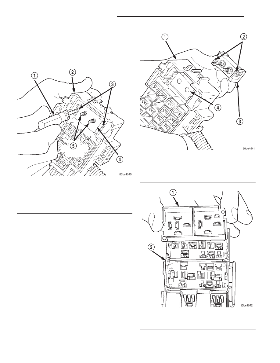
(1) Remove the PDC housing lower cover.
(2) From the top of the PDC housing, use a small
screwdriver or a terminal pick tool (Special Tool Kit
6680) to release the two latches that secure the B(+)
terminal module in the PDC (Fig. 15).
(3) Gently and evenly press the two B(+) terminal
studs down through the bus bar in the PDC.
(4) From the bottom of the PDC housing, remove
the B(+) terminal module from the PDC (Fig. 16).
PDC RELAY WEDGE
(1) Remove the PDC housing lower cover.
(2) Remove each of the relays from the PDC relay
wedge to be removed.
(3) From the bottom of the PDC housing, use a
small screwdriver or a terminal pick tool (Special
Tool Kit 6680) to release the two latches (yellow) that
secure the relay wedge to the PDC relay cassette.
(4) From the top of the PDC housing, remove the
relay wedge from the PDC relay cassette (Fig. 17).
Fig. 15 PDC B(+) Terminal Module Latches
1 – FROM SPECIAL TOOL KIT 6680
2 – PDC HOUSING
3 – LATCHES
4 – BUS BAR
5 – B(+) TERMINAL STUDS
Fig. 16 PDC B(+) Terminal Module Remove/Install
1 – PDC HOUSING
2 – LATCHES
3 – B(+) TERMINAL MODULE
4 – BUS BAR
Fig. 17 PDC Relay Wedge Remove/Install
1 – RELAY WEDGE (TYPICAL)
2 – PDC HOUSING
8O - 12
POWER DISTRIBUTION SYSTEMS
WJ
DISASSEMBLY AND ASSEMBLY (Continued)