Jeep Grand Cherokee WJ. Manual - part 131
 

  Index      Jeep     Jeep Grand Cherokee WJ - service repair manual 2001 year


Search            


Content   ..  129  130  131  132   ..


Jeep Grand Cherokee WJ. Manual - part 131


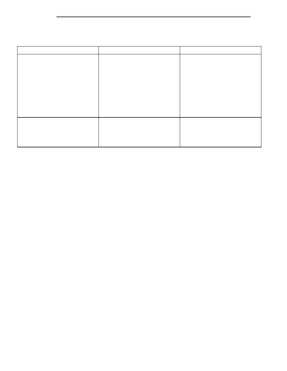
DAYTIME RUNNING LAMP

CONDITION

POSSIBLE CAUSES

CORRECTION

DAYTIME RUNNING LAMPS DO
NOT WORK

1. Poor connection at DRL module.
2. Parking brake engaged.
3. Parking brake circuit shorted to
ground.
4. Headlamp circuit shorted to
ground.
5. Defective DRL relay.
6. Body controller not programed
with Canadian country code.
7. DRL relay is missing.
8. Blown fuse for DRL.

1. Secure connector on DRL
module.
2. Disengage parking brake.
3. Check cluster telltale, refer to
Group 8W.
4. Refer to Group 8W.
5. Replace DRL relay.
6. Check country code.
7. Install DRL relay.
8. Replace fuse refer to Group 8W.

Clicking or chattering when DRL is
on.

1. Mechanical relay is installed in
the junction block.

1. Ensure that the DRL relay is
installed in the proper socket in
junction block, and that no
mechanical relay exists in the low
beam socket.

AUTO HEADLAMP SENSOR (AHL)

DESCRIPTION

The auto headlamp sensor is the key sensor for the

auto headlamp system. The sensor needs real sun-
light to properly register the light level. When auto
headlamps are enabled indoors, the headlamps may
be turned on. The sensor is located in the center of
the defroster grille at the base of the windshield.

OPERATION

There are no faults set in the Body Control Module

(BCM) for a bad or missing AHL Sensor. Symptom of
a missing sensor or unconnected sensor would be
that the Headlamps and Parklamps turn on when
the vehicle is started and there is a high level of
ambient light present (ie. daytime). Auto headlamps
should not function in the presence of daylight.

ADJUSTMENTS

VEHICLE PREPARATION FOR LAMP
ALIGNMENT

(1) Verify headlamp dimmer switch and high beam

indicator operation.

(2) Correct defective components that could hinder

proper lamp alignment.

(3) Verify proper tire inflation.
(4) Clean lamp lenses.
(5) Verify that luggage area is not heavily loaded.
(6) Fuel tank should be FULL. Add 2.94 kg (6.5

lbs.) of weight over the fuel tank for each estimated
gallon of missing fuel.

8L - 4

LAMPS

WJ

DIAGNOSIS AND TESTING (Continued)

LAMP ALIGNMENT SCREEN PREPARATION

(1) Position vehicle on a level surface perpendicu-

lar to a flat wall 7.62 meters (25 ft) away from front
of headlamp lens (Fig. 1).

(2) If necessary, tape a line on the floor 7.62

meters (25 ft) away from and parallel to the wall.

(3) Measure from the floor up 1.27 meters (5 ft)

and tape a line on the wall at the centerline of the
vehicle. Sight along the centerline of the vehicle
(from rear of vehicle forward) to verify accuracy of
the line placement.

(4) Rock vehicle side-to-side three times to allow

suspension to stabilize.

(5) Jounce front suspension three times by pushing

downward on front bumper and releasing.

(6) Measure the distance from the center of head-

lamp lens to the floor. Transfer measurement to the
alignment screen (with tape). Use this line for
up/down adjustment reference.

(7) Measure distance from the centerline of the

vehicle to the center of each headlamp being aligned.
Transfer measurements to screen (with tape) to each
side of vehicle centerline. Use these lines for left/
right adjustment reference.

Fig. 1 Headlamp Alignment Screen—Typical

1 – CENTER OF VEHICLE TO CENTER OF HEADLAMP LENS
2 – FLOOR TO CENTER OF HEADLAMP LENS
3 – 7.62 METERS (25 FEET)

4 – FRONT OF HEADLAMP
5 – VEHICLE CENTERLINE

WJ

LAMPS

8L - 5

ADJUSTMENTS (Continued)

HEADLAMP ADJUSTMENT

A properly aimed low beam will project the top

edge of the beam intensity pattern on the screen
from 25 mm (1 in.) above to 75 mm (3 in.) below
headlamp centerline. The side-to-side left edge of the
beam intensity pattern should be from 50 mm (2 in.)
left to 50 mm (2 in.) right of headlamp centerline
(Fig. 2).

(1) Clean front of the headlamps.
(2) Place headlamps on LOW beam.
(3) Cover front of the headlamp that is not being

adjusted.

(4) Turn adjustment screw (Fig. 3) and (Fig. 4)

until the top edge of the beam intensity pattern is
positioned within 25 mm (1 in.) above or 75 mm (3
in.) below the headlamp horizontal centerline.

(5) Cover front of the headlamp and adjust the

other headlamp beam as instructed below.

(6) Rotate the adjustment screw until the top edge

of the beam intensity pattern is positioned within 25
mm (1 in.) above or 75 mm (3 in.) below the head-
lamp horizontal centerline.

FOG LAMP ADJUSTMENT

Prepare an alignment screen. A properly aligned

fog lamp will project a pattern on the alignment
screen 100 mm (4 in.) below the fog lamp centerline
and straight ahead (Fig. 5).

Rotate the adjustment screw to adjust beam height

(Fig. 6).

Fig. 2 Low Beam Pattern

1 – LOW BEAM INTENSITY PATTERN (ISO-CANDELA CURVE)

Fig. 3 Headlamp Beam Adjustment Screw

1 – ADJUSTMENT SCREW LOCATION

Fig. 4 Headlamp Beam Adjustment

8L - 6

LAMPS

WJ

ADJUSTMENTS (Continued)

Fig. 5 Fog Lamp Alignment—Typical

1 – VEHICLE CENTERLINE
2 – CENTER OF VEHICLE TO CENTER OF FOG LAMP LENS
3 – HIGH-INTENSITY AREA
4 – FLOOR TO CENTER OF FOG LAMP LENS

5 – 100 mm (4 in.)
6 – 7.62 METERS (25 FEET)
7 – FRONT OF FOG LAMP

Fig. 6 Fog Lamp Adjustment

1 – ADJUSTMENT SCREW
2 – FOG LAMP

WJ

LAMPS

8L - 7

ADJUSTMENTS (Continued)


Content   ..  129  130  131  132   ..