Jeep Grand Cherokee WJ. Manual - part 96


  Index      Jeep     Jeep Grand Cherokee WJ - service repair manual 2001 year


Search            


Content   ..  94  95  96  97   ..


Jeep Grand Cherokee WJ. Manual - part 96


Vehicles equipped with a manual transmis-

sion, a floor mounted shifter, and NO LEVER
below the ignition key: 
The ignition key cylinder
must be depressed to allow it to be rotated into the
LOCK or ACCESSORY position. If it is difficult to
rotate the key to the LOCK or ACCESSORY position,
the lock mechanism within the steering column may
be defective. This mechanism is not serviceable. If
repair is necessary, the steering column assembly
must be replaced. Refer to Group 19, Steering for
procedures.

DIAGNOSIS AND TESTING

SPARK PLUG CONDITIONS
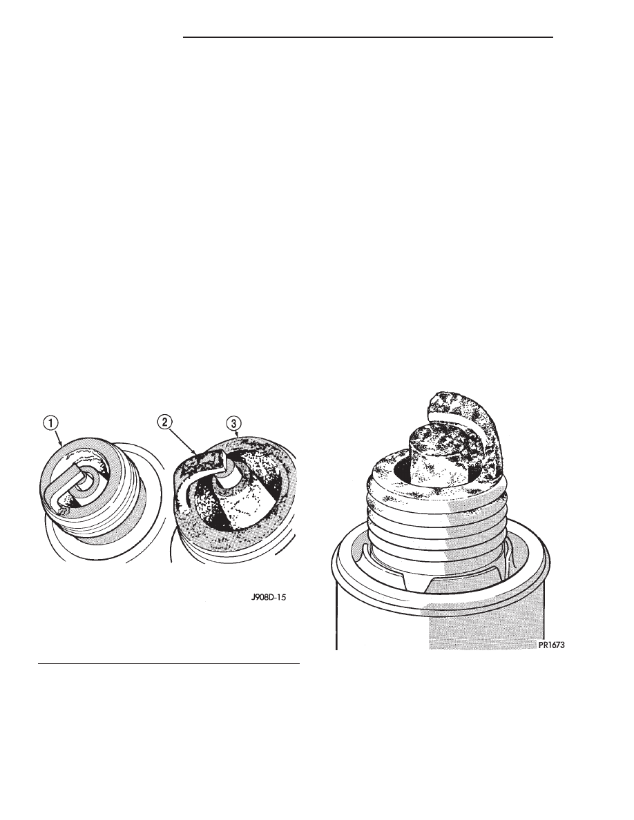
NORMAL OPERATING

The few deposits present on the spark plug will

probably be light tan or slightly gray in color. This is
evident with most grades of commercial gasoline
(Fig. 14). There will not be evidence of electrode
burning. Gap growth will not average more than
approximately 0.025 mm (.001 in) per 3200 km (2000
miles) of operation. Spark plugs that have normal
wear can usually be cleaned, have the electrodes
filed, have the gap set and then be installed.

Some fuel refiners in several areas of the United

States have introduced a manganese additive (MMT)
for unleaded fuel. During combustion, fuel with MMT
causes the entire tip of the spark plug to be coated
with a rust colored deposit. This rust color can be
misdiagnosed as being caused by coolant in the com-
bustion chamber. Spark plug performance may be
affected by MMT deposits.

COLD FOULING/CARBON FOULING

Cold fouling is sometimes referred to as carbon

fouling. The deposits that cause cold fouling are basi-
cally carbon (Fig. 14). A dry, black deposit on one or
two plugs in a set may be caused by sticking valves
or defective spark plug cables. Cold (carbon) fouling
of the entire set of spark plugs may be caused by a
clogged air cleaner element or repeated short operat-
ing times (short trips).

WET FOULING OR GAS FOULING

A spark plug coated with excessive wet fuel or oil

is wet fouled. In older engines, worn piston rings,
leaking valve guide seals or excessive cylinder wear
can cause wet fouling. In new or recently overhauled
engines, wet fouling may occur before break-in (nor-
mal oil control) is achieved. This condition can usu-
ally be resolved by cleaning and reinstalling the
fouled plugs.

OIL OR ASH ENCRUSTED

If one or more spark plugs are oil or oil ash

encrusted (Fig. 15), evaluate engine condition for the
cause of oil entry into that particular combustion
chamber.

ELECTRODE GAP BRIDGING

Electrode gap bridging may be traced to loose

deposits in the combustion chamber. These deposits
accumulate on the spark plugs during continuous
stop-and-go driving. When the engine is suddenly
subjected to a high torque load, deposits partially liq-
uefy and bridge the gap between electrodes (Fig. 16).

Fig. 14 Normal Operation and Cold (Carbon) Fouling

1 – NORMAL
2 – DRY BLACK DEPOSITS
3 – COLD (CARBON) FOULING

Fig. 15 Oil or Ash Encrusted

8D - 8

IGNITION SYSTEM

WJ

DESCRIPTION AND OPERATION (Continued)

This short circuits the electrodes. Spark plugs with
electrode gap bridging can be cleaned using standard
procedures.

SCAVENGER DEPOSITS

Fuel scavenger deposits may be either white or yel-

low (Fig. 17). They may appear to be harmful, but
this is a normal condition caused by chemical addi-
tives in certain fuels. These additives are designed to
change the chemical nature of deposits and decrease
spark plug misfire tendencies. Notice that accumula-
tion on the ground electrode and shell area may be
heavy, but the deposits are easily removed. Spark
plugs with scavenger deposits can be considered nor-
mal in condition and can be cleaned using standard
procedures.

CHIPPED ELECTRODE INSULATOR

A chipped electrode insulator usually results from

bending the center electrode while adjusting the
spark plug electrode gap. Under certain conditions,
severe detonation can also separate the insulator
from the center electrode (Fig. 18). Spark plugs with
this condition must be replaced.

PRE-IGNITION DAMAGE

Pre-ignition damage is usually caused by excessive

combustion chamber temperature. The center elec-
trode dissolves first and the ground electrode dis-
solves somewhat latter (Fig. 19). Insulators appear
relatively deposit free. Determine if the spark plug
has the correct heat range rating for the engine.
Determine if ignition timing is over advanced or if
other operating conditions are causing engine over-
heating. (The heat range rating refers to the operat-
ing temperature of a particular type spark plug.
Spark plugs are designed to operate within specific
temperature ranges. This depends upon the thick-
ness and length of the center electrodes porcelain
insulator.)

CAUTION: If the engine is equipped with copper
core ground electrode spark plugs, they must be
replaced with the same type/number spark plug as
the original. If another spark plug is substituted,
pre-ignition will result.

SPARK PLUG OVERHEATING

Overheating is indicated by a white or gray center

electrode insulator that also appears blistered (Fig.
20). The increase in electrode gap will be consider-
ably in excess of 0.001 inch per 2000 miles of opera-

Fig. 16 Electrode Gap Bridging

1 – GROUND ELECTRODE
2 – DEPOSITS
3 – CENTER ELECTRODE

Fig. 17 Scavenger Deposits

1 – GROUND ELECTRODE COVERED WITH WHITE OR

YELLOW DEPOSITS

2 – CENTER ELECTRODE

Fig. 18 Chipped Electrode Insulator

1 – GROUND ELECTRODE
2 – CENTER ELECTRODE
3 – CHIPPED INSULATOR

WJ

IGNITION SYSTEM

8D - 9

DIAGNOSIS AND TESTING (Continued)

tion. This suggests that a plug with a cooler heat
range rating should be used. Over advanced ignition
timing, detonation and cooling system malfunctions
can also cause spark plug overheating.

CAUTION: If the engine is equipped with copper
core ground electrode spark plugs, they must be
replaced with the same type/number spark plug as
the original. If another spark plug is substituted,
pre-ignition will result.

IGNITION SWITCH AND KEY LOCK CYLINDER

ELECTRICAL DIAGNOSIS

For ignition switch electrical schematics, refer to

Ignition Switch in Group 8W, Wiring Diagrams.

MECHANICAL DIAGNOSIS (KEY DIFFICULT TO
ROTATE)

Vehicles equipped with an automatic trans-

mission and a floor mounted shifter: a cable is
used to connect the interlock device in the steering
column assembly, to the transmission floor shift
lever. This interlock device is used to lock the trans-
mission shifter in the PARK position when the key
lock cylinder is rotated to the LOCKED or ACCES-
SORY position. The interlock device within the steer-
ing column is not serviceable. If repair is necessary,
the steering column assembly must be replaced.
Refer to Group 19, Steering for procedures.

If the ignition key is difficult to rotate to or from

the LOCK or ACCESSORY position, it may not be
the fault of the key cylinder or the steering column
components. The brake transmission shift interlock
cable may be out of adjustment. Refer to Brake
Transmission Shift Interlock Cable Adjustment in
Group 21, Transmissions for adjustment procedures.

Vehicles equipped with an automatic trans-

mission and a steering column mounted shifter:
an interlock device is located within the steering col-
umn. This interlock device is used to lock the trans-
mission shifter in the PARK position when the key
lock cylinder is in the LOCKED or ACCESSORY
position. If it is difficult to rotate the key to or from
the LOCK or ACCESSORY position, the interlock
device within the steering column may be defective.
This device is not serviceable. If repair is necessary,
the steering column assembly must be replaced.
Refer to Group 19, Steering for procedures.

Vehicles equipped with a manual transmis-

sion and a floor mounted shifter: on certain mod-
els, a lever is located on the steering column behind
the ignition key lock cylinder. The lever must be
manually operated to allow rotation of the ignition
key lock cylinder to the LOCK or ACCESSORY posi-
tion. If it is difficult to rotate the key to the LOCK or
ACCESSORY position, the lever mechanism may be
defective. This mechanism is not serviceable. If
repair is necessary, the steering column assembly
must be replaced. Refer to Group 19, Steering for
procedures.

On other models, the ignition key cylinder must be

depressed to allow it to be rotated into the LOCK or
ACCESSORY position. If it is difficult to rotate the
key to the LOCK or ACCESSORY position, the lock
mechanism within the steering column may be defec-
tive. This mechanism is not serviceable. If repair is
necessary, the steering column assembly must be
replaced. Refer to Group 19, Steering for procedures.

Fig. 19 Pre-ignition Damage

1 – GROUND ELECTRODE STARTING TO DISSOLVE
2 – CENTER ELECTRODE DISSOLVED

Fig. 20 Spark Plug Overheating

1 – BLISTERED WHITE OR GRAY COLORED INSULATOR

8D - 10

IGNITION SYSTEM

WJ

DIAGNOSIS AND TESTING (Continued)

REMOVAL AND INSTALLATION

SPARK PLUGS

REMOVAL

On the 4.0L 6–cylinder engine, the spark plugs are

located below the coil rail assembly. On the 4.7L V–8
engine, each individual spark plug is located under
each ignition coil.

(1) 4.0L 6–Cylinder Engine: Prior to removing

spark plug, spray compressed air around spark plug
hole and area around spark plug. This will help pre-
vent foreign material from entering combustion
chamber.

(2) 4.7L V–8 Engine: Prior to removing spark plug,

spray compressed air around base of ignition coil at
cylinder head. This will help prevent foreign material
from entering combustion chamber.

(3) On the 4.0L engine the coil rail assembly must

be removed to gain access to any/all spark plug.
Refer to Ignition Coil Removal/Installation. On the
4.7L V-8 engine each individual ignition coil must be
removed to gain access to each spark plug. Refer to
Ignition Coil Removal/Installation.

(4) Remove spark plug from cylinder head using a

quality socket with a rubber or foam insert. If
equipped with a 4.7L V-8 engine, also check condition
of coil o-ring and replace as necessary.

(5) Inspect spark plug condition. Refer to Spark

Plug Conditions.

CLEANING

The plugs may be cleaned using commercially

available spark plug cleaning equipment. After clean-
ing, file center electrode flat with a small point file or
jewelers file before adjusting gap.

CAUTION: Never use a motorized wire wheel brush
to clean spark plugs. Metallic deposits will remain
on spark plug insulator and will cause plug misfire.

ADJUSTMENT

Check spark plug gap with a gap gauge tool. If the

gap is not correct, adjust it by bending ground elec-
trode (Fig. 21). Never attempt to adjust gap by
bending center electrode.

INSTALLATION

CAUTION: The 4.7L V–8 engine is equipped with
copper core ground electrode spark plugs. They
must be replaced with the same type/number spark
plug as the original. If another spark plug is substi-
tuted, pre-ignition will result.

Special care should be taken when installing spark

plugs into cylinder head spark plug wells. Be sure

plugs do not drop into plug wells as ground straps
may be bent resulting in a change in plug gap, or
electrodes can be damaged.

Always tighten spark plugs to specified torque.

Over tightening can cause distortion resulting in a
change in spark plug gap or a cracked porcelain insu-
lator.

(1) Start spark plug into cylinder head by hand to

avoid cross threading.

(2) 4.0L 6–Cylinder Engine: Tighten spark plugs to

35-41 N·m (26-30 ft. lbs.) torque.

(3) 4.7L V–8 Engine: Tighten spark plugs to 27

N·m (20 ft. lbs.) torque.

(4) 4.7L V–8 Engine: Before installing coil(s),

check condition of coil o-ring and replace as neces-
sary. To aid in coil installation, apply silicone to coil
o-ring.

(5) Install ignition coil(s). Refer to Ignition Coil

Removal/Installation.

IGNITION COIL—4.0L ENGINE

REMOVAL

A one-piece coil rail assembly containing three

individual coils is used on the 4.0L engine (Fig. 22).
The coil rail must be replaced as one assembly. The
bottom of the coil is equipped with 6 individual rub-
ber boots (Fig. 22) to seal the 6 spark plugs to the
coil. Inside each rubber boot is a spring. The spring
is used for an electrical contact between the coil and

Fig. 21 Setting Spark Plug Gap—Typical

1 – GAUGE
2 – SPARK PLUG

WJ

IGNITION SYSTEM

8D - 11


Content   ..  94  95  96  97   ..