Jeep Grand Cherokee WJ. Manual - part 83
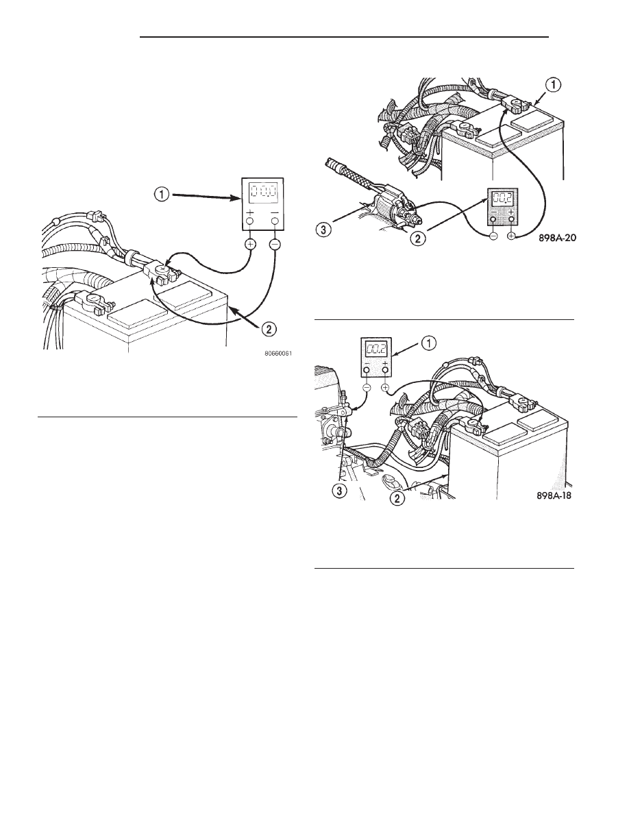
(2) Connect the positive lead of the voltmeter to
the battery positive terminal post. Connect the nega-
tive lead of the voltmeter to the battery positive cable
terminal clamp (Fig. 16). Rotate and hold the ignition
switch in the Start position. Observe the voltmeter. If
voltage is detected, correct the poor connection
between the battery positive cable terminal clamp
and the battery positive terminal post.
(3) Connect the voltmeter to measure between the
battery positive cable terminal clamp and the starter
solenoid B(+) terminal stud (Fig. 17). Rotate and hold
the ignition switch in the Start position. Observe the
voltmeter. If the reading is above 0.2 volt, clean and
tighten the battery positive cable eyelet terminal con-
nection at the starter solenoid B(+) terminal stud.
Repeat the test. If the reading is still above 0.2 volt,
replace the faulty battery positive cable.
(4) Connect the voltmeter to measure between the
battery negative cable terminal clamp and a good
clean ground on the engine block (Fig. 18). Rotate
and hold the ignition switch in the Start position.
Observe the voltmeter. If the reading is above 0.2
volt, clean and tighten the battery negative cable
eyelet terminal connection to the engine block.
Repeat the test. If the reading is still above 0.2 volt,
replace the faulty battery negative cable.
SERVICE PROCEDURES
BATTERY CHARGING
Battery charging is the means by which the bat-
tery can be restored to its full voltage potential. A
battery is fully-charged when:
• All of the battery cells are gassing freely during
battery charging.
• A green color is visible in the sight glass of the
battery built-in test indicator.
• Three hydrometer tests, taken at one-hour inter-
vals, indicate no increase in the temperature-cor-
rected specific gravity of the battery electrolyte.
• Open-circuit voltage of the battery is 12.4 volts
or above.
Fig. 16 Test Battery Positive Connection Resistance
- Typical
1 – VOLTMETER
2 – BATTERY
Fig. 17 Test Battery Positive Cable Resistance -
Typical
1 – BATTERY
2 – VOLTMETER
3 – STARTER MOTOR
Fig. 18 Test Ground Circuit Resistance - Typical
1 – VOLTMETER
2 – BATTERY
3 – ENGINE GROUND
8A - 16
BATTERY
WJ
DIAGNOSIS AND TESTING (Continued)