Jeep Grand Cherokee WJ. Manual - part 57


  Index      Jeep     Jeep Grand Cherokee WJ - service repair manual 2001 year


Search            


Content   ..  55  56  57  58   ..


Jeep Grand Cherokee WJ. Manual - part 57


INSPECTION

The piston is made from a phenolic resin (plastic

material) and should be smooth and clean.

The piston must be replaced if cracked or scored.

Do not attempt to restore a scored piston surface by
sanding or polishing.

CAUTION: If the caliper piston is replaced, install
the same type of piston in the caliper. Never inter-
change phenolic resin and steel caliper pistons.
The pistons, seals, seal grooves, caliper bore and
piston tolerances are different.

The bore can be lightly polished with a brake

hone to remove very minor surface imperfections
(Fig. 83). The caliper should be replaced if the bore is
severely corroded, rusted, scored, or if polishing
would increase bore diameter more than 0.025 mm
(0.001 inch).

ADJUSTMENTS

BRAKE LAMP SWITCH

(1) Press and hold brake pedal in applied position.
(2) Pull switch plunger all the way out to fully

extended position.

(3) Release brake pedal. Then pull pedal lightly

rearward. Pedal will set plunger to correct position
as pedal pushes plunger into switch body. Switch will
make ratcheting sound as it self adjusts.

CAUTION: Booster damage may occur if the pedal
pull exceeds 20 lbs.

PARKING BRAKE SHOE

(1) Remove wheel and tire assemblies.
(2) Secure rotor with two wheel nuts.

(3) Remove rubber access plug from back of splash

shield.

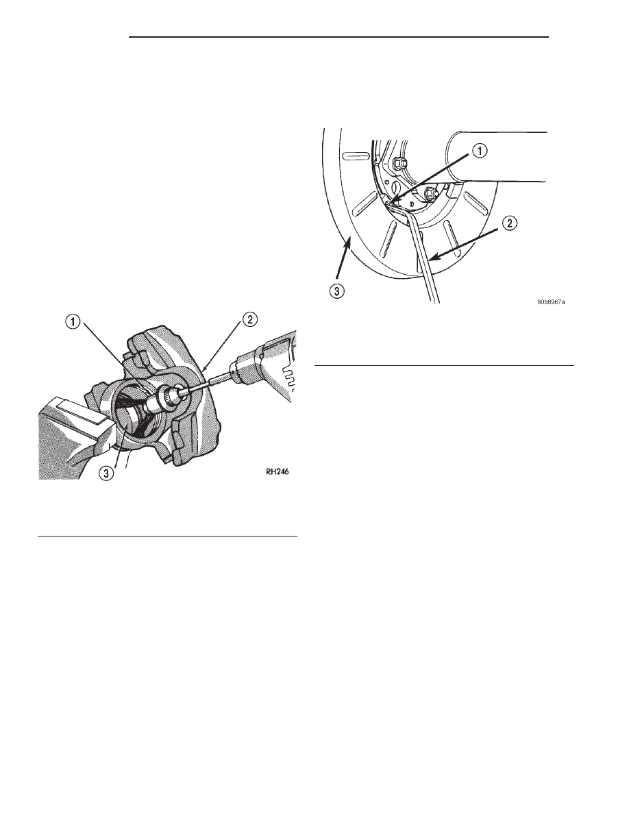
(4) Insert brake tool through access hole in splash

shield (Fig. 84). Position tool at bottom of star wheel.

(5) Rotate star wheel upward direction to expand

shoes (while facing front of vehicle).

(6) Expand shoes until light drag is experienced.

Then back off adjuster screw only enough to elimi-
nate drag.

(7) Install plug in splash shield access hole.
(8) Install wheel and tire assemblies.

SPECIFICATIONS

BRAKE FLUID

The brake fluid used in this vehicle must conform

to DOT 3 specifications and SAE J1703 standards.
No other type of brake fluid is recommended or
approved for usage in the vehicle brake system. Use
only Mopar brake fluid or an equivalent from a
tightly sealed container.

CAUTION: Never use reclaimed brake fluid or fluid
from an container which has been left open. An
open container of brake fluid will absorb moisture
from the air and contaminate the fluid.

CAUTION: Never use any type of a petroleum-
based fluid in the brake hydraulic system. Use of
such type fluids will result in seal damage of the
vehicle brake hydraulic system causing a failure of
the vehicle brake system. Petroleum based fluids
would be items such as engine oil, transmission
fluid, power steering fluid, etc.

Fig. 83 Polishing Piston Bore

1 – SPECIAL HONE
2 – CALIPER
3 – PISTON BORE

Fig. 84 Park Brake Shoe Adjustment

1 – ACCESS HOLE
2 – BRAKE ADJUSTING TOOL
3 – SPLASH SHIELD

5 - 36

BRAKES

WJ

CLEANING AND INSPECTION (Continued)

BRAKE COMPONENTS

Front Disc Brake Caliper

Type . . . . . . . . . . . . . . . . . . . . . . . . . . . . Floating
Pistons . . . . . . . . . . . . . . . . . . . 48 mm (1.889 in.)

Front Disc Brake Rotor

Type . . . . . . . . . . . . . . . . . . . . . . . . . . Ventilated
Diameter . . . . . . . . . . . . . . . . . . 305 mm (12 in.)
Max. Runout . . . . . . . . . . . . . 0.05 mm (0.002 in.)
Max. Thickness Variation . . . . . . . . . . 0.0127 mm

(0.0005 in.)

Min. Thickness . . . . . . . . . . 24.5 mm (0.9646 in.)

Rear Disc Brake Caliper

Type . . . . . . . . . . . . . . . . . . . . . . . . . . . . Floating
Piston . . . . . . . . . . . . . . . . . . . 48 mm (1.889 in.)

Rear Disc Brake Rotor

Type . . . . . . . . . . . . . . . . . . . . . . . . . . . . . . Solid
Diameter . . . . . . . . . . . . . . . . . . 305 mm (12 in.)
Max. Runout . . . . . . . . . . . . . 0.76 mm (0.003 in.)
Max. Thickness Variation . . . 0.0127 mm (0.0005

in.)

Min. Thickness . . . . . . . . . . . . 8.5 mm (0.335 in.)
Drum Max. Diameter . . . . . . 196 mm (7.7166 in.)

Brake Booster

Type . . . . . . . . . . . . . . . . . . . . . Dual Diaphragm

TORQUE CHART

DESCRIPTION

TORQUE

Brake Pedal

Support Bolt . . . . . . . . . 23-34 N·m (17-25 ft. lbs.)
Pivot Nut . . . . . . . . . . . 27-35 N·m (20-26 ft. lbs.)

Brake Booster

Mounting Nuts . . . . . . . . . . . 39 N·m (29 ft. lbs.)

Master Cylinder

Mounting Nuts . . . . . . . . . . . 25 N·m (18 ft. lbs.)
Primary Brake Line . . . . . . 16 N·m (144 in. lbs.)
Secondary Brake Line . . . . . 16 N·m (144 in. lbs.)

Front Caliper

Slide Pins . . . . . . . . . . . 29-41 N·m (21-30 ft. lbs.)
Anchor Bolts . . . . . . . . 90-115 N·m (66-85 ft. lbs.)
Brake Hose Banjo Bolt . . . . . . 31 N·m (23 ft. lbs.)
Bleed Screw . . . . . . . . . . . . . 16 N·m (144 in. lbs.)

Rear Caliper

Slide Pins . . . . . . . . . . . 29-41 N·m (21-30 ft. lbs.)
Anchor Bolts . . . . . . . . 90-115 N·m (66-85 ft. lbs.)
Brake Hose Banjo Bolt . . . . . . 31 N·m (23 ft. lbs.)
Bleed Screw . . . . . . . . . . . . . 16 N·m (144 in. lbs.)

SPECIAL TOOLS

BASE BRAKES

Installer Caliper Dust Boot 8280

Handle C-4171

Adapter Pressure Bleeder 6921

WJ

BRAKES

5 - 37

SPECIFICATIONS (Continued)

ANTILOCK BRAKES

TABLE OF CONTENTS

page

page

DESCRIPTION AND OPERATION

ANTILOCK BRAKE SYSTEM . . . . . . . . . . . . . . . . 38
CONTROLLER ANTILOCK BRAKES . . . . . . . . . . . 39
ELECTRONIC BRAKE DISTRIBUTION . . . . . . . . . 39
HYDRAULIC CONTROL UNIT. . . . . . . . . . . . . . . . 39
G-SWITCH . . . . . . . . . . . . . . . . . . . . . . . . . . . . . . 40
ABS WARNING LAMP . . . . . . . . . . . . . . . . . . . . . 40
WHEEL SPEED SENSORS AND TONE WHEEL . . 40

DIAGNOSIS AND TESTING

ANTILOCK BRAKES. . . . . . . . . . . . . . . . . . . . . . . 41

SERVICE PROCEDURES

BLEEDING ABS BRAKE SYSTEM . . . . . . . . . . . . 41

REMOVAL AND INSTALLATION

CONTROLLER ANTILOCK BRAKES . . . . . . . . . . . 41
FRONT WHEEL SPEED SENSOR . . . . . . . . . . . . 42
HYDRAULIC CONTROL UNIT/CONTROLLER

ANTILOCK BRAKES . . . . . . . . . . . . . . . . . . . . . 42

REAR WHEEL SPEED SENSOR . . . . . . . . . . . . . 43
G-SWITCH . . . . . . . . . . . . . . . . . . . . . . . . . . . . . . 44

SPECIFICATIONS

TORQUE CHART . . . . . . . . . . . . . . . . . . . . . . . . . 45

DESCRIPTION AND OPERATION

ANTILOCK BRAKE SYSTEM

DESCRIPTION

The purpose of the antilock system is to prevent

wheel lockup during periods of high wheel slip. Pre-
venting lockup helps maintain vehicle braking action
and steering control.

The hydraulic system is a three channel design.

The front brakes are controlled individually and the
rear brakes in tandem.

The ABS electrical system is separate from other

vehicle electrical circuits. A separate controller oper-
ates the system.

OPERATION

The antilock CAB activates the system whenever

sensor signals indicate periods of high wheel slip.
High wheel slip can be described as the point where
wheel rotation begins approaching 20 to 30 percent of
actual vehicle speed during braking. Periods of high
wheel slip occur when brake stops involve high pedal
pressure and rate of vehicle deceleration.

Battery voltage is supplied to the CAB ignition ter-

minal when the ignition switch is turned to Run posi-
tion. The CAB performs a system initialization
procedure at this point. Initialization consists of a
static and dynamic self check of system electrical
components.

The static check occurs after the ignition switch is

turned to Run position. The dynamic check occurs
when vehicle road speed reaches approximately 30

kph (18 mph). During the dynamic check, the CAB
briefly cycles the pump and solenoids to verify oper-
ation.

If an ABS component exhibits a fault during ini-

tialization, the CAB illuminates the amber warning
light and registers a fault code in the microprocessor
memory.

ANTILOCK BRAKING

The antilock system prevents lockup during high

slip conditions by modulating fluid apply pressure to
the wheel brake units.

Brake fluid apply pressure is modulated according

to wheel speed, degree of slip and rate of decelera-
tion. A sensor at each wheel converts wheel speed
into electrical signals. These signals are transmitted
to the CAB for processing and determination of
wheel slip and deceleration rate.

The ABS system has three fluid pressure control

channels. The front brakes are controlled separately
and the rear brakes in tandem. A speed sensor input
signal indicating a high slip condition activates the
CAB antilock program.

Two solenoid valves are used in each antilock con-

trol channel. The valves are all located within the
HCU valve body and work in pairs to either increase,
hold, or decrease apply pressure as needed in the
individual control channels.

The solenoid valves are not static during antilock

braking. They are cycled continuously to modulate
pressure. Solenoid cycle time in antilock mode can be
measured in milliseconds.

5 - 38

BRAKES

WJ

ELECTRONIC BRAKE DISTRIBUTION

DESCRIPTION

The electronic brake distribution (EBD) functions

like a rear proportioning valve. The EBD system uses
the ABS system to control the slip of the rear wheels
in partial braking range. The braking force of the
rear wheels is controlled electronically by using the
inlet and outlet valves located in the HCU.

OPERATION

Upon entry into EBD the inlet valve for the rear

brake circuit is switched on so that the fluid supply
from the master cylinder is shut off. In order to
decrease the rear brake pressure the outlet valve for
the rear brake circuit is pulsed. This allows fluid to
enter the low pressure accumulator (LPA) in the
HCU resulting in a drop in fluid pressure to the rear
brakes. In order to increase the rear brake pressure
the outlet valve is switched off and the inlet valve is
pulsed. This increases the pressure to the rear
brakes. This will continue until the required slip dif-
ference is obtained. At the end of EBD braking (no
brake application) the fluid in the LPA drains back to
the master cylinder by switching on the outlet valve
and draining through the inlet valve check valve. At
the same time the inlet valve is switched on to pre-
vent a hydraulic short circiut in case of another
brake application.

The EBD will remain functional during many ABS

fault modes. If the red and amber warning lamps are
illuminated the EBD may have a fault.

CONTROLLER ANTILOCK BRAKES

DESCRIPTION

The CAB is mounted to the HCU and operates the

ABS system (Fig. 1) separate from other vehicle elec-
trical circuits.

OPERATION

The CAB voltage source is through the ignition

switch in the RUN position. The CAB contains dual
microprocessors. A logic block in each microprocessor
receives identical sensor signals. These signals are
processed and compared simultaneously. The CAB
contains a self check program that illuminates the
ABS warning light when a system fault is detected.
Faults are stored in a diagnostic program memory
and are accessible with the DRB scan tool. ABS
faults remain in memory until cleared, or until after
the vehicle is started approximately 50 times. Stored
faults are not erased if the battery is disconnected.

HYDRAULIC CONTROL UNIT

DESCRIPTION

The HCU consists of a valve body, pump motor,

and wire harness (Fig. 1).

OPERATION

Accumulators in the valve body store extra fluid

released to the system for ABS mode operation. The
pump is used to clear the accumulator of brake fluid
and is operated by a DC type motor. The motor is
controlled by the CAB.

The

valves

modulate

brake

pressure

during

antilock braking and are controlled by the CAB.

The HCU provides three channel pressure control

to the front and rear brakes. One channel controls
the rear wheel brakes in tandem. The two remaining
channels control the front wheel brakes individually.

During antilock braking, the solenoid valves are

opened and closed as needed. The valves are not
static. They are cycled rapidly and continuously to
modulate pressure and control wheel slip and decel-
eration.

During normal braking, the HCU solenoid valves

and pump are not activated. The master cylinder and
power booster operate the same as a vehicle without
an ABS brake system.

During antilock braking, solenoid valve pressure

modulation occurs in three stages, pressure increase,
pressure hold, and pressure decrease. The valves are
all contained in the valve body portion of the HCU.

PRESSURE DECREASE

The outlet valve is opened and the inlet valve is

closed during the pressure decrease cycle.

Fig. 1 Controller Antilock Brakes

1 – HCU
2 – MOTOR
3 – CAB

WJ

BRAKES

5 - 39

DESCRIPTION AND OPERATION (Continued)


Content   ..  55  56  57  58   ..