Jeep Grand Cherokee WJ. Manual - part 16
needle bearing lying at the bottom of the cap will
prevent proper assembly.
(4) Press the bearing cap into the yoke bore
enough to install a snap ring.
(5) Install a snap ring.
(6) Repeat Step 3 and Step 4to install the opposite
bearing cap. If the joint is stiff or binding, strike the
yoke with a soft hammer to seat the needle bearings.
(7) Add grease to lube fitting, if equipped.
(8) Install the propeller shaft.
CLEANING AND INSPECTION
SINGLE CARDAN JOINT
(1) Clean all the universal joint yoke bores with
cleaning solvent and a wire brush.
(2) Inspect the yokes for distortion, cracks, and
worn bearing cap bores.
ADJUSTMENTS
FRONT PROPELLER SHAFT MEASUREMENT
This measurement is to be taken with the shaft
installed and the vehicle at proper ride height.
(1) Place vehicle on floor or drive-on hoist with full
weight of vehicle on suspension.
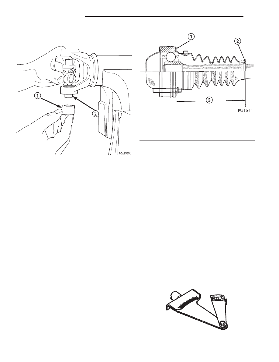
(2) Measure the distance from the face of the CV
joint cup to the end of the CV joint boot (Fig. 19).
(3) The correct length is 142.7 mm (5.61 in.).
(4) If the measurement is not correct, the wrong
shaft may have been installed or a mating compo-
nent (front axle or transfer case) may be installed
incorrectly. Investigate and correct as necessary.
SPECIFICATIONS
TORQUE
FRONT PROPELLER SHAFT
DESCRIPTION
TORQUE
Bolts, Transfer Case
Companion Flange . . . . . 32 N·m (23.5 ft. lbs.)
Bolts, Pinion Companion Flange . . . . . . 32 N·m
(23.5 ft. lbs.)
REAR PROPELLER SHAFT
DESCRIPTION
TORQUE
Bolts, Rear Yoke . . . . . . . . . . . 19 N·m (14 ft. lbs.)
SPECIAL TOOLS
PROPELLER SHAFT
Fig. 18 Install Bearing On Trunnion
1 – BEARING CAP
2 – TRUNNION
Fig. 19 Measurement
1 – CV JOINT CUP
2 – CV BOOT END
3 – MEASUREMENT
Inclinometer—7663
3 - 10
PROPELLER SHAFTS
WJ
DISASSEMBLY AND ASSEMBLY (Continued)